


5 Electrical installation
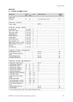
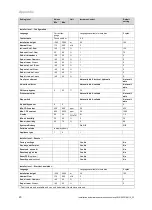
12
Installation and maintenance instructions recoVAIR 0020188110_03
circuit breaker (depending on the country)
to switch off the product's power supply.
▶
Secure the power supply against being
switched on again.
▶
Check that there is no voltage in the con-
nections.
5.1
Connecting external components in the
product's connection area
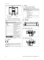
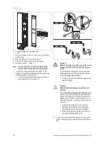
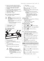
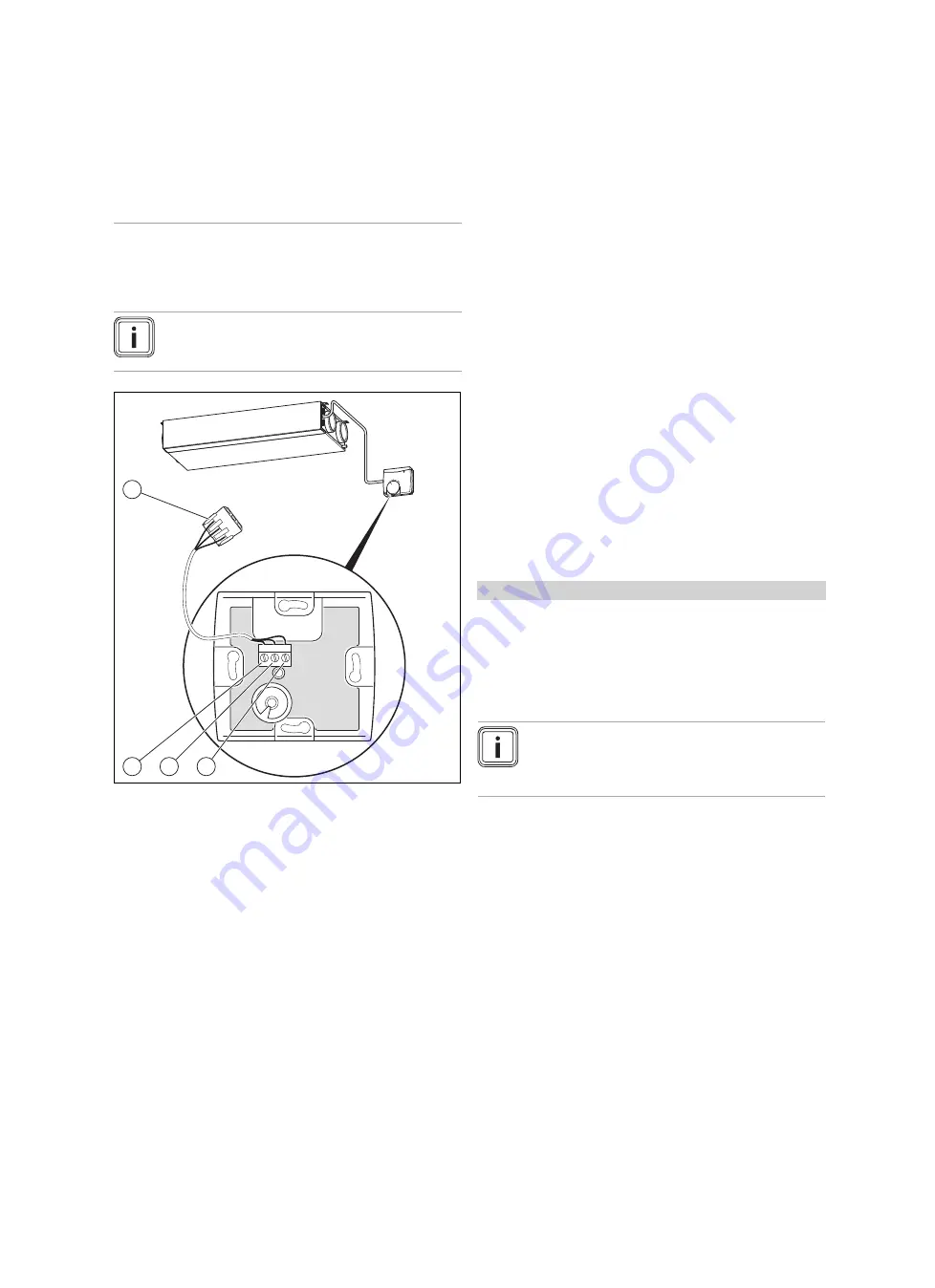
5.1.1
Connecting the stage switch
Note
If a Vaillant controller is connected, the step
switch will not work.
3
2
1
3
4
2
1
1
Connection 1 to GND
connection
2
Connection 2 to LED
connection
3
Connection 3 to con-
nection V+
4
Connection plug (in the
unit)
1.
Open the stage switch by removing the housing.
2.
Connect the connection cable in the connection area of
the stage switch.
–
Terminal assignment: GND connection to connec-
tion 1/LED connection to connection 2/V+ connec-
tion to connection 3
3.
Connect the connection cable to the connection plug
(4)
in the connection area for external components of the
product.
5.1.2
Connecting the air quality sensors
▶
Connect the air-quality sensors in the connection area
for external components of the product (
→
Installation
instructions for the air-quality sensors).
5.1.3
Connecting the VRC 700 system control
▶
Connect the control to the eBUS connection in the con-
nection area for external components of the product (
→
System control installation instructions).
–
Connection type: eBUS line
–
Controller: Compatibility as of VRC 470/4
▶
If the DCF signal is not decoded, set the date and time
on the control (
→
System control installation instructions).
5.2
Installing and connecting the frost
protection element
▶
Install the frost protection element (
→
Installation instruc-
tions for the frost protection element).
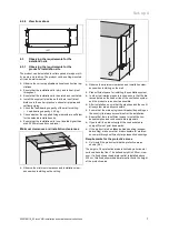
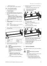
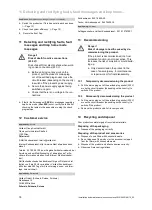
5.3
Connecting the bypass
1.
Open the product. (
→
Page 11)
2.
Remove the existing screen from the bypass insertion
point.
3.
Insert the new screen (with an opening for the bypass
motor) into the bypass insertion point.
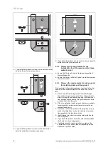
4.
Push the bypass shaft onto the bypass motor.
5.
Connect the relevant cable (directly to the left of the
insertion point) to the bypass motor.
6.
Insert the bypass motor into the screen for the bypass
insertion point.
7.
Close the product. (
→
Page 11)
Conditions
: The bypass motor was connected retroactively
▶
Navigate to
Menu
→
Installer level
→
Configuration
→
Bypass
and change the setting.
–
Setting:
Available
Installer level
–
Overview (
→
Page 19)
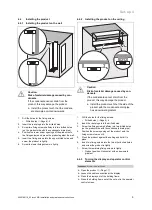
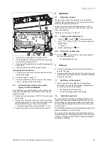
5.4
Connecting the VR 32 bus coupler
Note
If you want a system control to control other
Vaillant heat generators in addition to the product,
the VR 32 bus coupler is required.
1.
Open the product. (
→
Page 11)
Opening the electronics box
2.
Remove the cover from the electronics box by releasing
the latching lugs from their anchoring point.


