


11 Detecting and rectifying faults, fault messages and limp home…
18
Installation and maintenance instructions recoVAIR 0020188110_03
Conditions
: No maintenance message is shown in the display.
▶
Switch the product on if this has not already been done.
(
→
Page 13)
▶
Check the system efficiency. (
→
Page 15)
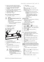
8.
Secure the front flap.
11 Detecting and rectifying faults, fault
messages and limp home mode
messages
Danger!
Risk of death from live connections
(230 V)!
Risk of death from electric shock when work-
ing on live connections (230 V).
▶
Before carrying out any work on the
product, pull the product's mains plug
out of the earthed plug socket or use the
circuit breaker (depending on the country)
to switch off the product's power supply.
▶
Secure the power supply against being
switched on again.
▶
Check that there is no voltage in the con-
nections.
▶
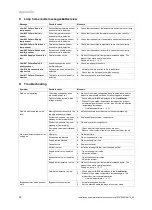
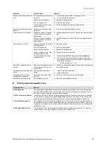
If faults, fault messages (
F.XXX
) or messages regarding
limp home mode (
Lhm.XXX
) occur, rectify the fault after
checking the tables in the appendix or using the check
programmes.
12 Customer service
Applicability:
Austria
Vaillant Group Austria GmbH
Clemens-Holzmeister-Straße 6
1100 Wien
Österreich
E-Mail Kundendienst: termin@vaillant.at
Internet Kundendienst: http://www.vaillant.at/werkskunden-
dienst/
Telefon: 05
7050
‑
2100 (zum Regionaltarif österreichweit, bei
Anrufen aus dem Mobilfunknetz ggf. abweichende Tarife -
nähere Information erhalten Sie bei Ihrem Mobilnetzbetrei-
ber)
Der flächendeckende Kundendienst für ganz Österreich ist
täglich von 0 bis 24 Uhr erreichbar. Vaillant Kundendienst-
techniker sind 365 Tage für Sie unterwegs, sonn- und feier-
tags, österreichweit.
Applicability:
Switzerland
Vaillant GmbH (Schweiz, Suisse, Svizzera)
Riedstrasse 12
CH-8953 Dietikon
Schweiz, Svizzera, Suisse
Kundendienst: 044
74429
‑
29
Techn. Vertriebssupport: 044
74429
‑
19
Applicability:
Germany
Auftragsannahme Vaillant Kundendienst: 021
91
5767901
13 Decommissioning
Danger!
Risk of damage to health caused by de-
commissioning the product.
If the product is decommissioned, the frost
protection function is no longer active. This
increases the risk of moisture or mould build-
ing up.
▶
Only decommission the product in the
case of an emergency, for maintenance
or repair work or for final disassembly.
13.1
Temporarily decommissioning the product
▶
Pull the mains plug out of the earthed plug socket (230 V)
or use the circuit breaker (depending on the country) to
switch off the product.
13.2
Permanently decommissioning the product
▶
Pull the mains plug out of the earthed plug socket (230 V)
or use the circuit breaker (depending on the country) to
switch off the product.
▶
Remove the product and all of its components.
14 Recycling and disposal
Your product consists largely of recyclable materials.
Disposing of the packaging
▶
Dispose of the packaging correctly.
Disposing of the product and accessories
▶
Dispose of used filters with household waste.
▶
Do not dispose of the product or the accessories (apart
from the filters) with household waste.
▶
Dispose of the product and all accessories correctly.
▶
Observe all relevant regulations.


