0020323586_00 Installation and maintenance instructions
47
B
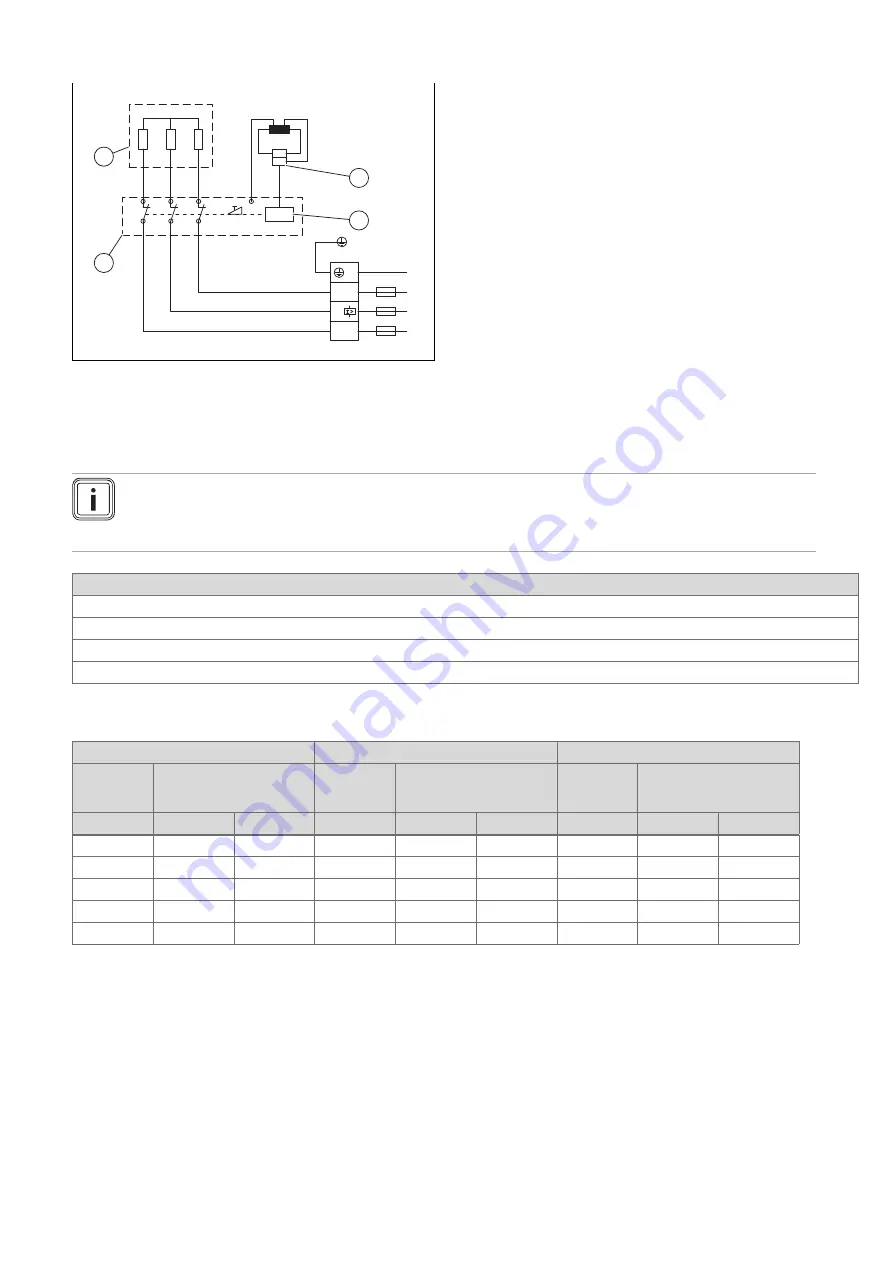
Wiring diagram
L
L1’
L2’
L3’
U
F
θ>
L
L
4
3
2
1
1
Safety cut-out
2
Electronic safety switch
3
Printed circuit board
4
Heating element
C
Inspection and maintenance work
–
Overview
Note
The table below lists the manufacturer's minimum requirements with regard to inspection and maintenance. If na-
tional regulations and directives require shorter inspection and maintenance intervals, you should observe these
instead of the intervals listed in the table.
Maintenance work
Check that the product functions correctly
Descale the product
Clean the water filter in the cold water connector
Cleaning the valve's flow regulator on the draw-off point
D
Standard specification
Standard specification at 15 °C
Standard specification at 20 °C
Standard specification at 25 °C
Specific
resistance
ρ ≥
Specific conductivity
σ ≤
Specific
resistance
ρ ≥
Specific conductivity
σ ≤
Specific
resistance
ρ ≥
Specific conductivity
σ ≤
Ω
cm
mS/m
µ
S/cm
Ω
cm
mS/m
µ
S/cm
Ω
cm
mS/m
µ
S/cm
900
111
1111
800
125
1250
735
136
1361
1000
100
1000
890
112
1124
815
123
1227
1100
91
909
970
103
1031
895
112
1117
1200
83
833
1070
93
935
985
102
1015
1300
77
769
1175
85
851
1072
93
933
Summary of Contents for 0010044426
Page 167: ......


