4
Operation
Instructions for use turboMAX pro
4
Initial checks before turning ON
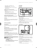
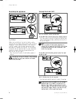
Open the service valves
• Ensure the cold water service valve is open. This can
be checked by opening a hot water tap and ensuring
water flows.
• Ensure that the service valves in the heating flow and
return (2 and 1) and the gas service valve (3) are open.
The flow, return and gas
service valves are open when the line marking
has the same direction as the pipe.
• The pressure relief valve (4) is provided for safety
reasons and must not be interfered with.
Fig. B.3: Opening service valves
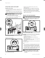
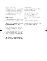
Check the water contents
Fig. B.4: Checking the water level
• Check the water contents of the system on the
pressure gauge (4).
• The needle on the pressure gauge should be within
the green band (between 1 and 1.5 bar). If the needle
displays a value below 0.8 bar when the appliance is
cold, follow the instructions left by your installer to
refill the system. Alternatively, your installer should be
called to refill the system.
Domestic hot water operation
The boiler should only be used when the heating
system contains water. Use of the boiler without
water may cause damage to the boiler or its
components.
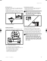
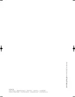
Fig. B.5: Domestic hot water supply
Setting the maximum domestic hot water temperatu-
re control
• Turn the main switch (1) to the „l“ position.
• The domestic hot water
temperature can be adjusted using the hot water
temperature control (2).
• Turn the control clockwise to increase the temperature
and anti-clockwise to decrease the
temperature.
As a guide for normal circumstances set the knob to the
1 o´clock position.
Note:
This control adjusts the maximum domestic hot water
temperature. If adjusting the control upwards appears
to have no effect on the temperature, then the boiler
is already operating at full output for the selected flow
rate. If hotter water is required the flow rate should be
reduced by partially closing the hot water tap.
If you live in a hard water area please do not set
the control knob above the mid (12 o´clock)
position to prevent excessiv scale formation
(fig. B.5).
I
0
C
o
C
o
1
2
I
0
4
I
0
2
3
1
4
833689_22GB_032005 09.03.2005 17:13 Uhr Seite 4


