36
Installation and maintenance manual atmoCRAFT
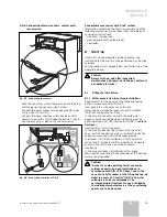
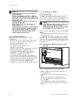
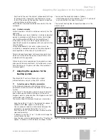
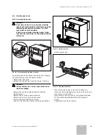
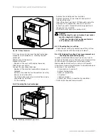
Fig. 8.5 Fitting the burner
If it is necessary to also clean the heat exchanger,
proceed as per Section 8.4.2. Cleaning the heat
exchanger.
Otherwise re-fit the burner.
Proceed as follows:
• Replace all the seals with original new ones.
Slide the burner back in.
Connect the gas connection pipe.
• Replace all the electrical connections previously
removed.
• Perform a function test on the control and safety
devices (see Section 8.3).
• Check the boiler, exhaust gas installation and gas
connection for tightness.
• Fit the cladding.
8.4.2 Cleaning the heat exchanger
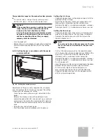
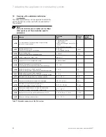
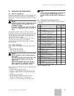
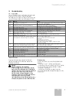
Fig. 8.6 Brushing the exhaust gas ducts
• Remove the cladding and the insulation.
• Remove the burner as described in Section 8.4.1
Cleaning the burner.
• Clean the exhaust gas ducts (
1
) thoroughly using the
cleaning brush supplied (
2
). You can access the
exhaust gas ducts through the cleaning aperture in
the exhaust gas manifold.
• Re-fit the burner again (see Section 8.4.1).
Caution!
After cleaning, the gas and exhaust gas routes
must be checked for tightness.
• Perform a function test on the control and
safety devices (see Section 8.3).
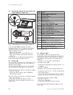
8.4.3 Checking the gas setting
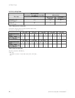
• Check the gas setting by comparison of the gas flow
on the gas meter with the values in Table 6.2.
8.4.4 Performing the exhaust gas measurement and
checking the combustion quality
In order to determine the exhaust gas losses, t
h
e CO
2
content in the exhaust gas, the exhaust gas temperature
and the room air temperature must be measured.
Modern electronic exhaust gas analysis instruments
allow several measuring parameters to be determined or
calculated at the same time.
- CO
2
content (or O
2
content)
- Exhaust temperature
- Room air temperature
- CO content
- Chimney draught
- Exhaust gas losses (automatically calculated)
• Perform the required measurements.
8 Inspection and maintenance
Summary of Contents for atmocraft
Page 1: ...VK 654 9 1654 9 atmoCRAFT DE AT GB...
Page 2: ......
Page 44: ...835553_02 DEATGB 092006...

