7 Eliminating the fault
14
Installation and maintenance instructions atmoMAG 0020271943_00
6.4
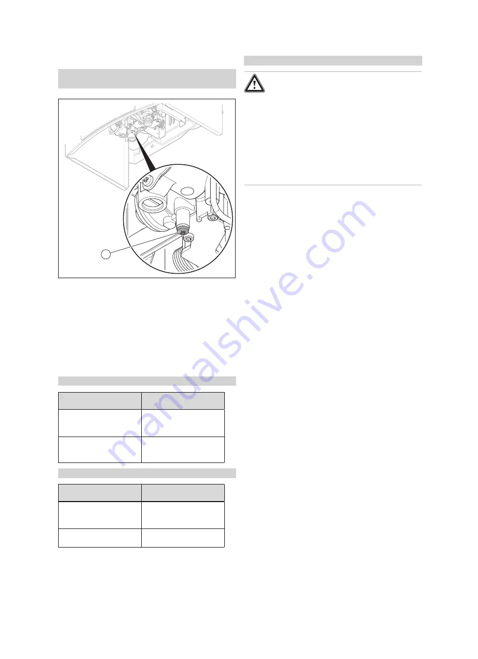
Checking the gas flow pressure
Applicability:
Germany
OR Belgium
1
▶
Close the gas stopcock.
▶
Unscrew the sealing screw
(1)
from the test nipple on the
gas valve assembly.
▶
Remove the seal.
▶
Connect a manometer to the test nipple on the gas valve
assembly.
▶
Open the gas stopcock.
▶
Start up the product in accordance with the operating
instructions and draw off domestic hot water.
▶
Measure the gas flow pressure.
Applicability:
Germany
Gas family
Permissible gas flow pres-
sure
Natural gas
G20
G25
1.7
–
2.5 kPa (17
–
25 mbar)
1.8-2.5 kPa (18-25 mbar)
Liquid gas
G31
4.25-5.75 kPa (42.5-
57.5 mbar)
Applicability:
Belgium
Gas family
Permissible gas flow pres-
sure
Natural gas
G20
G25
1.7
–
2.5 kPa (17
–
25 mbar)
2.0-3.0 kPa (20-30 mbar)
Liquid gas
G31
2.5
–
4.5 kPa (25
–
45 mbar)
Conditions
: Gas connection pressure not in the permissible range
Danger!
Risk of material damage and operating
faults caused by incorrect gas flow pres-
sure.
If the gas flow pressure lies outside the per-
missible range, this can cause operating
faults in and damage to the product.
▶
Do not make any adjustments to the
product.
▶
Check the gas installation.
▶
Do not start up the product.
▶
If you are unable to remedy the fault, contact the gas
supply company.
▶
Close the gas stopcock.
▶
Remove the pressure gauge.
▶
Position the seal on the sealing screw.
▶
Screw the sealing screw
(1)
into the test nipple on the
gas valve assembly again.
▶
Open the gas stopcock.
▶
Check the test nipple for gas tightness.
6.5
Checking leak-tightness
▶
Check the gas pipe and the hot water circuit for leak-
tightness.
▶
Check that the flue system has been installed correctly.
6.6
Handing the product over to the operator
1.
Explain to the operator how the safety devices work and
where they are located.
2.
Inform the operator how to handle the product. Answer
any questions the operator may have.
3.
Draw special attention to the safety instructions which
the operator must follow.
4.
Inform the operator of the necessity to have the product
maintained according to the specified intervals.
5.
Pass all of the instructions and documentation for the
product to the operator for safe-keeping.
6.
Inform the operator about measures taken to ensure the
supply of combustion air and flue gas guiding, and in-
struct the operator that he must not make any changes.
7
Eliminating the fault
▶
Use the table that is included in the appendix to eliminate
the fault.
▶
After each time you eliminate a fault, check that the flue
gas sensor is working without any problems.
▶
If you are unable to eliminate the fault, contact Vaillant
Customer Service.
8
Inspection and maintenance
▶
Adhere to the minimum inspection and maintenance in-
tervals. The inspection may require maintenance to be


