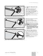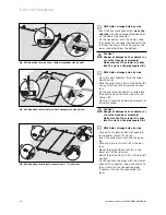
4.4 Interconnection
diagram
h
Note
Observe the planning information when dimen-
sioning the field volume flow.
n
Field arrangement side by side
h
Note
If you connect 1 to 5 collectors one after
another, the hydraulic connections can be laid
one below the other on one side.
1
4
5
...
Fig. 4.3 Field arrangement side by side for 1 - 5 collectors
h
Note
If you connect 6 or more collectors one after
another, the hydraulic connections must be ar-
ranged diagonally, to force a complete flow.
1
12
11
2
...
max. 12
Fig. 4.4 Field arrangement side by side for 6 - 12 collectors
u
Field arrangement on top of each other
max. 2
Fig. 4.5 Field arrangement on top of each other
4.5 Hydraulic
connection
preparation
4.5.1 On-roof
mounting
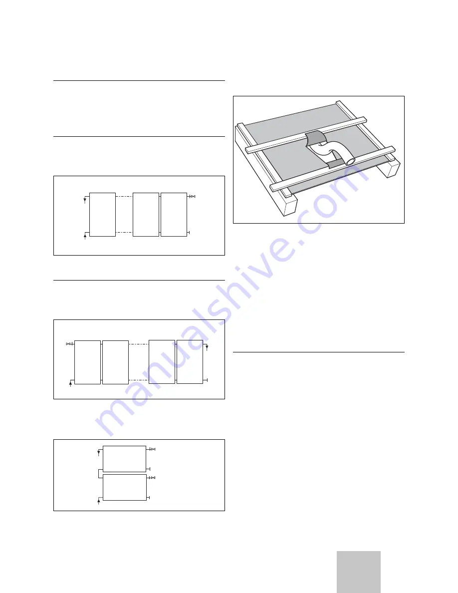
Fig. 4.7 Passing the pipe through the sarking membrane
If there is a sarking membrane, proceed as follows:
• Cut the sarking membrane vee-shaped.
• Fold the upper, larger tab on the roof batten above,
and the lower, smaller tab on the roof batten below.
• Fix the sarking membrane tight to the roof batten.
This ensure that the dampness flows away to the side.
• With the roofs activated, cut out a hole with the com-
pass saw.
• Work the roofing felt as described for the sarking
membrane.
4.5.2 Flat
roof
installation
a
Caution!
The roof skin can break and cause lack of tight-
ness!
When installing the roof sealing surfaces, make
sure the roof skin is adequately protected.
• Place large protection mats under the system.
• If the frame is screwed directly, check the sealing of
the building shell.
9
Installation manual auroTHERM 0020057143_02
Before installation 4
GB


