background image

5.3 Collector 

installation

1

2

3

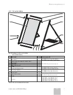
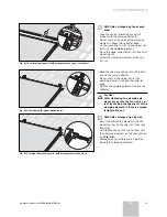
Fig. 5.2 Preparing the frame

• Open the frames.

a

 Caution!

Observe Table 5.1 for determining the 
required load!

With screwed connection on the roof

•  Fix the lower telescopic section with bolt 

and safety clip.

2

1

2

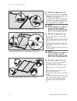
Fig. 5.3 Mounting the gravel trays

If gravel trays are used:

•  Slide the gravel tray (

1

) on the floor sec-

tion.

Collector 
position

Number of gravel trays per frame

w

2

s

3

Table 5.3 Number of gravel trays

•  Apply the safety clamps (

2

) from the top in 

the floor sections (2 x frame) to fix the 
gravel tray.

•  Fix the lower telescopic section with bolt 

and safety clip.

60°

45°

30°

1

2

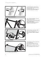
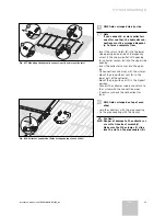
Fig. 5.4 Frame assembly

•  Insert the telescopic sections into each 

other, until the holes of the desired angular 
position are placed one above the other.

h

 Note

You can choose 30°, 45° or 60° 
(standard: 45°).

•  Insert the retaining pin into the corre-

sponding hole (

1

).

•  Fix the retaining pin with the safety clip (

2

).

Installation manual auroTHERM 0020057143_02

12

5 Flat roof installation

Summary of Contents for auroTHERM VFK 145 H/V

Page 1: ...auroTHERM VFK 125 VFK 135 D VFK 140 D VFK 145 H V VFK 150 H V ES GB NL PT On roof Flat roof ...

Page 2: ...delivery 6 4 2 1 On roof mounting 6 4 2 2 Flat roof installation 7 4 3 Collector field packaging 8 4 4 Interconnection diagram 9 4 5 Hydraulic connection preparation 9 4 5 1 On roof mounting 9 4 5 2 Flat roof installation 9 4 6 Required tools 10 5 Flat roof installation 10 5 1 Collector position and field arrangement 10 5 2 Weighting and arrangement of the frames 11 5 3 Collector installation 12 6...
Page 3: ...ion one for the vertical posi tion Besides collectors in the collector field can be arranged side by side and on top of each other Generally the installation steps and the instructions described in this manual are valid for both collector positions and field arrangements Any different installation steps are clearly pointed out w With horizontal collector position s With vertical collector position...

Page 4: ...he units col lectors can reach 200 C Do not perform maintenance work under direct sunlight a Caution Collector damage In order to install flat collectors according to the installation manual a qualified engineer is required The installation should be performed only by qualified engineers 3 1 Technical Guidance The system must be installed in accordance with all rel evant and applicable national re...
Page 5: ...s and where appro priate netting Areas around the scaffolding should be zoned off and marked with suitable warning signs to a suitable distance to protect persons from falling objects Workers should have available and use personal protec tive equipment as necessary This would include equip ment such as fall protection systems safety gloves goggles dust masks as well as any specialised equip ment t...

Page 6: ...ergy system has been started up a Caution Collectors may be damaged by incorrect stor age Always store the collectors in a dry place and protected from the elements Caution System error function due to air bubbles To fill the system use the fill trolley article number 0020042548 to avoid air bubbles Use the manual air vent installed on the collec tor field Alternatively install the Vaillant Solar ...

Page 7: ...r collector sensor 1 0020059891 Hydraulic connection kit 3 Return inlet 1 4 Lower plug 1 5 Upper plug with vent 1 6 Clamp 4 7 Roof anchor type S for beaver tail etc 4 0020055184 8 Roof anchor type P for pantile 4 0020055174 9 Stair bolt mounting kit 4 0020059897 10 Hydraulic connections 2 0020055181 Hydraulic extension kit 11 Clamp 4 12 Collector 1 0010004455 auroTHERM VFK 145 V 0010004457 auroTHE...

Page 8: ...onnection kit 3 Return inlet 1 4 Lower plug 1 5 Upper plug with vent 1 6 Clamp 4 7 Frame with clamping element 1 0020055206 Base vertical frame kit 0020055207 Base horizontal frame kit 8 Gravel tray optional 2 3 0020059904 Gravel tray kit 2 pieces 0020059905 Gravel tray kit 3 pieces 9 Safety clamps 2 10 Hydraulic connections 2 0020055181 Hydraulic extension kit 11 Clamp 4 12 Collector 1 0010004455...

Page 9: ... P article number 0020059896 1 Anchor extension kit 2 type S article number 0020059895 Horizontal rail anodized Article No 0020059898 1 2 Vertical collector position Hyd connection kit article number 0020059891 1 1 Hyd connection kit article number 0020059894 1 Anchor set 1 type P article number 0020055174 1 1 Anchor set 2 type S article number 0020055184 Anchor set 3 stair bolt Article number 002...

Page 10: ...preparation 4 5 1 On roof mounting Fig 4 7 Passing the pipe through the sarking membrane If there is a sarking membrane proceed as follows Cut the sarking membrane vee shaped Fold the upper larger tab on the roof batten above and the lower smaller tab on the roof batten below Fix the sarking membrane tight to the roof batten This ensure that the dampness flows away to the side With the roofs activ...

Page 11: ...0 Besides the height of the mounting rails is variable in order to compensate for small floor irregularities 5 1 Collector position and field arrangement Vaillant flat collectors are available in different versions one for horizontal position one for vertical position Generally the installation steps and the instructions described in this manual are valid for both collector positions Any different...

Page 12: ... 30 45 60 C D A B F B F B F Vertical 1 1136 1283 4400 1740 6100 2080 7200 2357 2 2300 1150 3 3563 1263 4 4826 5 6089 6 7352 7 8615 8 9878 9 11141 10 12404 C C F Horizontal 1 1650 883 3100 1173 4100 1387 4800 1812 2 3900 1950 3 5963 2063 4 8026 5 10089 6 12152 7 14215 8 16278 9 18341 10 20404 Dimension A can vary by 50 mm in connection with dimension E Possible only with 4 offset gravel trays 1 Ang...

Page 13: ...s per frame w 2 s 3 Table 5 3 Number of gravel trays Apply the safety clamps 2 from the top in the floor sections 2 x frame to fix the gravel tray Fix the lower telescopic section with bolt and safety clip 60 45 30 1 2 Fig 5 4 Frame assembly Insert the telescopic sections into each other until the holes of the desired angular position are placed one above the other h Note You can choose 30 45 or 6...

Page 14: ...onnection With screwed connection on the roof Assembly frames based on the number of collectors to be installed hNote For load weights and distances please see Tab 5 1 and 5 2 Fix the frames on the roof a Caution The roof skin can break and cause lack of tightness When installing the roof sealing sur faces make sure the roof skin is ade quately protected Fig 5 7 Fixing and blocking the mounting ra...

Page 15: ...the mounting rails and fix them to the frame clamping elements Compensate any difference in height by moving the clamping elements 1 Fig 5 10 Hooking the collector Place the collector with the lower edge in the section of the mounting rail Make sure that the upper part 1 of the clamping element is above the collector edge Fig 5 11 Positioning the upper mounting rail Slide the upper mounting rail u...

Page 16: ...ectors with the clamps 2 Tighten both clamping elements of the first collector a Caution Danger of damage to the collector as a result of incorrect assembly Make sure that the clamp A slides into the slot on the pipe coupler B 1 2 3 4 Fig 5 14 Mounting the hydraulic connections 1 5 collectors Connect the supply outlet with opening for collector sensor 1 on top Insert the collector sensor into the ...

Page 17: ...ckly and reliably with at tachment clips To ensure a good adaptation to the dif ferent roofings three different roof anchors are availa ble Type P for standard tiles and bricks e g pantile Type S for flat shingles and tiles e g beaver tail slate and extremely high protruding tiles e g Medi terranean clay tiles Stair bolt mounting kit for universal fixing e g corru gated slabs sheet with trapezoida...

Page 18: ... 24 24 24 24 24 24 24 24 24 900 24 24 24 24 24 24 36 24 36 24 1200 24 24 24 24 36 24 48 36 48 36 7 700 28 28 28 28 28 28 28 28 28 28 900 28 28 28 28 28 28 42 28 42 28 1200 28 28 28 28 42 28 56 42 56 42 Field of application according to EN 1991 T 1 3 Anchor Fmax type S type P 1 875 kN Wind load based on the design loads according to EN 1991 T 1 3 the following minimum distances among collectors mus...

Page 19: ...ion is reduced by approx 20 25 mm Take care that there is adequate clearance on the anchors therefore A B C D Fig 6 2 Distances with field arrangement on top of each other u With fields arranged on top of each other Mount the anchors for the mounting rails at the following distances Distance in mm A 1245 1220 B 2500 2480 C 200 300 D 1460 1660 Pre assembly dimension Finished dimension During final ...

Page 20: ...chor 3 Loosen the upper bolt with the socket combination wrench SW 13 until the height of the roof anchor can be adjusted 4 Position the roof anchor at the same height of the pantiles so that the upper part of the anchor is on the roofing and tighten the bolt with the socket combina tion wrench SW 13 5 Screw the roof anchor to the rafters with the 3 sup plied bolts 6 Slide the pantiles back to the...

Page 21: ...r beaver tail a Caution Before installation on the roof batten check the load capacity of the roof batten If necessary replace it 2 1 4 3 Fig 6 6 Fixing the roof anchor type S 1 Uncover the rafters or the roof batten where needed For distances please see Tab 6 2 and 6 3 2 Position the roof anchor Take care anchor is tightly fixed and pre tensioned on the roof batten toothing engaged 5 Tighten the ...

Page 22: ...responding posi tion For distances please see Tab 6 2 and 6 3 2 Tighten the stair bolt to the rafters through the pan tile 3 Screw the lower nut against the pantiles and tighten it until the seal sufficiently seals the opening 4 Position the central nut so that after inserting the an chor upper part the front contact area is on the roof ing 5 Screw the second nut and tighten it SW 17 6 Detach the ...

Page 23: ...ontal position Compensate any difference in height by moving the clamping elements Pull the clamping element upward now it can be moved and it engages again when released 1 Fig 6 10 Hooking the collector Place the collector with the lower edge on the mounting rail and hook it to the clamp ing elements Make sure that the upper part 1 of the clamping element is above the collector edge Tighten the c...

Page 24: ...he upper mounting rail until it flush es with the lower collector Make sure that the upper part of the clamping element is above the collector edge Tighten the clamping elements above the collector a Caution After tightening the clamping ele ments make sure the tension is cor rect by shaking the upper part of the clamping element If it can be moved retighten the nut Fig 6 13 Joining the mounting r...

Page 25: ...e the collector on the first collector 2 paying attention to the hydraulic connec tors Fix the hydraulic connectors inserted into the opening up to the limit stop with the clamps 3 Tighten all remaining clamping elements of the roof anchors a Caution Danger of damage to the collector as a result of incorrect assembly Make sure that the clamp A slides into the slot on the pipe coupler B 1 2 3 4 Fig...

Page 26: ...collector sensor into the open ing Fix connections and plugs with the clamps Mount the plug without vent 3 in the lower part of the collector Mount the plug with vent 1 in the highest position Connect the collector supply and return to the system with the connection pipes If necessary check the connections for leaks a 1 2 Fig 6 18 Collector connection fields arrangedn top of each other u With fiel...

Page 27: ...d recycling the components when after years of reliable operation they must be disposed of 9 Vaillant Customer Service and warranty 9 1 Vaillant warranty Vaillant provide a full parts and labour warranty for this appliance The appliance must be installed by a suitably competent person in accordance with the Gas Safety Installation and Use Regulations 1998 and the manu facturer s instructions In th...

Page 28: ...Absorber mm Aluminium vacuum coated 0 5 x 1178 x 1978 Coating High selective blue D 95 H 5 Glass covering mm 3 2 thickness x 1233 x 2033 Glass type Solar safety glass prismatic structure Solar safety glass anti reflex coating Transmission W 91 W 96 Back wall insulation mm W m2 K kg m3 40 O 0 035 U 55 Edge insulation none Efficiency Ko 80 1 H 79 1 V 84 2 H 83 3 V Heat capacity Ws m2 K 9700 H 8200 V...

Page 29: ...Installation manual auroTHERM 0020057143_02 28 10 Technical data VFK 145 H VFK 150 H 80 2033 1178 1233 1978 66 5 66 5 1100 1223 5 Fig 10 1 Scale drawing VFK 145 H VFK 150 H ...

Page 30: ...29 Installation manual auroTHERM 0020057143_02 Technical data 10 VFK 145 V VFK 150 V 80 2033 1233 1978 1223 5 80 1178 79 79 1875 Fig 10 2 Scale drawing VFK 145 V VFK 150 V GB ...

Page 31: ...0020057143_02 ESGBNLPT 102008 ...

Reviews: