background image

2 Safety

8

Installation manual auroTHERM exclusive 0020077994_02

2.4

Intended use

2.4.1 Intended use

Vaillant

auroTHERM VTK

tube collectors are used for solar

heating support and for solar-supported hot water genera-
tion.

2.4.2 Suitability of the equipment

The collectors must only be operated with Vaillant ready-
mixed solar fluid. Passing heating water or hot water dir-
ectly through the collectors constitutes improper use.

2.4.3 Improper use

Any use which is not explicitly mentioned in the chapter
"Intended use" (

Page 8) is deemed improper.

Any other or additional use does not comply with the in-
tended use. Any direct commercial or industrial use is also
deemed to be improper. The manufacturer/supplier is not
liable for any damage resulting from such use. The user
alone bears the risk.

2.4.3.1 Combination with other components

Vaillant

auroTHERM VTK

tube collectors must only be

combined with components (fastenings, connections, etc.)
and system parts that are supplied by Vaillant. The use of
other components or system parts shall be considered as
improper use.

2.4.3.2 Installation in or on vehicles

Installation of the Vaillant

auroTHERM VTK

tube collector

in or on a vehicle is not permissible and is considered im-
proper use. Units that are not classed as vehicles are those
that are installed in a fixed and permanent location (known
as "fixed installation").

2.4.4 Other applicable documents

Intended use includes the following:

observance of accompanying operating, installation and
servicing instructions for Vaillant products as well as for
other parts and components of the system,

installing and fitting the unit in accordance with the
boiler and system approval,

compliance with all inspection and maintenance condi-
tions listed in the instructions.

2.5

Regulations (directives, laws, standards)

2.5.1

Installation regulations

Regulations

Applies to:

Great Britain

Technical Guidance

The system must be installed in accordance with all relev-
ant and applicable national regulations, and must be in-
stalled to suit site conditions. Observe all national regula-
tions, including:

Working at Heights Regulations 2005

Health and Safety at Work Act 1974

Electricity at Work Regulations 1989

IEE Wiring Regulations BS 7671

Lightning protection requirements

Equipotential bonding of electrical installations.

Related documents

The installation of the solar system must be in accordance
with the relevant requirements of Health and Safety Doc-
ument No. 635 (The Electricity at Work Regulations 1989),
BS7671 (IEE Wiring Regulations) and the Water Supply (Wa-
ter Fitting) Regulations 1999, or The Water Bylaws 2000
(Scotland). It should also be in accordance with the relevant
requirements of the Local Authority, Building Regulations,
The Building Regulations (Scotland), The Building Regula-
tions (Northern Ireland) and the relevant recommendations
of the following British Standards:

BS EN 806: Specification for installations inside buildings
conveying water for human consumption

BS 6700: Services supplying water for domestic use
within buildings and their curtilages

BS 5449 Forced circulation hot water central heating
systems for domestic premises. Note: only up to 45 kW

BS. 6880 Low temperature hot water heating systems of
output greater than 45 kW

Part 1 Fundamental and design considerations.

Part 2 Selection of equipment

Part 3 Installation, commissioning and maintenance

BS 6114: Expansion vessels using an internal diaphragm
for unvented hot water supply systems

BS. 4814 Specification for: Expansion vessels using an in-
ternal diaphragm, for sealed hot water heating systems

Unvented hot water systems must comply with building
regulation G section 3

2.5.2 Regulations for the prevention of accidents

Applies to:

Great Britain

When carrying out works such as solar installation work it is
necessary to do so in a safe and workman like manner, tak-
ing due care of any aspects of the works that could result in

Summary of Contents for auroTHERM VTK 1140/2

Page 1: ...For the competent person Installation manual auroTHERM exclusive VTK 570 2 VTK 1140 2 GB IE Installation manual ...

Page 2: ...er manufacturer Vaillant GmbH Berghauser Str 40 D 42859 Remscheid Telefon 49 21 91 18 0 Telefax 49 21 91 18 28 10 info vaillant de www vaillant de Vaillant GmbH 2012 These instructions or extracts thereof may only be printed with the written consent of Vaillant GmbH All designations of products in these instructions are brand names trade marks of the companies in ques tion We reserve the right to ...

Page 3: ...tability of the equipment 8 2 4 3 Improper use 8 2 4 4 Other applicable documents 8 2 5 Regulations directives laws standards 8 2 5 1 Installation regulations 8 2 5 2 Regulations for the prevention of accidents 8 2 6 CE label 9 3 Description of the unit 10 3 1 Type overview 10 3 2 Information on the identification plate 10 3 3 Purpose of the unit 10 4 On roof fitting and installation 11 4 1 Prepar...

Page 4: ...t and lack of tightness 58 6 6 Cleaning collectors 58 6 7 Checking brackets and collector components for firm seating 58 6 8 Check the pipe insulations for damage 58 6 9 Replacing damaged pipe insulations 58 6 10 Disposing of damaged pipe insulations 58 7 Troubleshooting 59 7 1 Spare parts for repair 59 7 2 Carrying out repairs 59 7 2 1 Replace leaking collectors 59 7 2 2 Disposing of defective co...

Page 5: ...ents All installation instructions for the component parts and components of the solar plant must be observed when installing the collectors These installation instructions are enclosed with the vari ous system parts and supplementary components 1 3 Document storage Document handover Pass this installation manual and all other applicable documents and if necessary any required tools to the system ...

Page 6: ...he user or others or of damage to the unit and other property in the event of im proper use or use for which it is not intended 2 3 2 Risk of death due to improper fastening systems The collectors may fall due to improper fastening systems Only the combination of Vailllant collectors and Vaillant fastening systems has been tested This combination can withstand the forces caused by additional wind ...

Page 7: ...lightning protection device in accordance with applicable regulations 2 3 11 Frost damage due to water in the solar circuit Water residue in the collector may freeze in frosty condi tions and damage the collector Never fill or flush the collector with water Only fill and flush the collector with Vaillant ready mixed solar fluid Check the solar fluid regularly with an antifreeze tester 2 3 12 Mater...

Page 8: ...lies to Great Britain Technical Guidance The system must be installed in accordance with all relev ant and applicable national regulations and must be in stalled to suit site conditions Observe all national regula tions including Working at Heights Regulations 2005 Health and Safety at Work Act 1974 Electricity at Work Regulations 1989 IEE Wiring Regulations BS 7671 Lightning protection requiremen...

Page 9: ...riate netting Areas around the scaffolding should be zoned off and marked with suit able warning signs to a suitable distance to protect per sons from falling objects Workers should have available and use personal protective equipment as necessary This would include equipment such as fall protection systems safety gloves goggles dust masks as well as any special ised equipment that may be in use s...

Page 10: ...d requirements for the Solar Keymark Read the installation manual VTK 570 2 VTK 1140 2 Type designation VTK Vaillant tube collector 570 1140 Collector output 2 Unit generation auroTHERM exclusive Unit type Vacuum tube collector Tube collector AG Gross area VF Liquid volume m Weight l Dimensions Qmax Max output tstgf Stagnation temperature Pmax Max permissible operating pressure Serial No Bar code ...

Page 11: ...nstallation When fitting and installing the collectors you must ob serve the chapter Safety 4 1 Preparing for fitting and installation 4 1 1 Delivery transport and positioning 4 1 1 1 Storing collectors To prevent moisture from penetrating into the collector always store the collectors dry and in a weatherproof area ...

Page 12: ...stallation set basic set 1 pc 6 VTK installation set extension set 1 pc 7 Stop valve 2 way VTK for parallel connection 1 pc 8 Roof bracket type P for pantile basic set 4 pc Roof bracket type P for pantile extension set on top of each other 2 pc 9 Roof bracket type S for beaver tail etc basic set 4 pc Roof bracket type S for beaver tail etc extension set on top of each other 2 pc 10 Roof bracket ty...

Page 13: ...02 auroTHERM exclusive Installation manual 13 11 Hanger bolt fastening set basic set 4 pc Hanger bolt fastening set extension set on top of each other 2 pc 12 Long base hook type P 4 pc Use the image to check that the installation sets are complete ...

Page 14: ... connection for the collectors Ensure that the solar fluid flows through the collectors either from left to right or from right to left Conditions Number of VTK 1140 2 collectors 1 7 max 7 x VTK 1140 2 Switch up to 7 VTK 1140 2 units in series according to the 14 m aperture surface area Conditions Parallel connection aperture surface area 7 m Always connect as many collectors as possible in series...

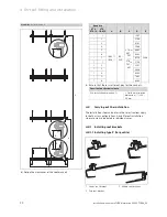
Page 15: ...Tichelmann system in order to avoid pressure losses in the connection tubes 4 1 4 Preparing the roof duct Caution Building damage due to penetrating wa ter If the roof duct is not prepared properly water may penetrate the building interior Ensure that the roof duct is prepared properly 1 Make a v shaped cut in the roofing felt membrane 2 Fold the upper wider flap onto the roof batten above and fol...

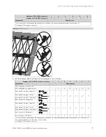
Page 16: ...tion set extension set 1 2 3 4 5 6 Roof bracket set type P pantile 1 2 2 2 3 2 4 2 5 2 6 2 7 2 Roof bracket set type S slate Roof bracket set type S flat slate Roof anchor set hanger bolt Rail set 2 pcs VTK 1140 2 1 2 3 4 5 6 7 1 1 set for connecting to the pipelines the collectors are connected together using the extension set 2 valid up to 700 m above sea level Number of VTK 1140 2 collectors 1 ...

Page 17: ...row 1 2 3 4 5 6 7 Components Required sets VTK installation set basic set 2 1 VTK installation set extension set 2 4 6 8 10 12 Roof bracket set type P pantile A 1 2 2 2 3 2 4 2 5 2 6 2 7 2 Roof bracket set type S slate Roof bracket set type S flat slate Roof anchor set hanger bolt Roof bracket set type P pantile B 1 2 2 2 3 2 4 2 5 2 6 2 7 2 Roof bracket set type S slate Roof bracket set type S fl...

Page 18: ...tallation set extension set 3 6 9 12 15 18 Roof bracket set type P pantile A 1 2 2 2 3 2 4 2 5 2 6 2 7 2 Roof bracket set type S slate Roof bracket set type S flat slate Roof bracket set type P pantile B 2 2 4 2 6 2 8 2 10 2 12 2 14 2 Roof bracket set type S slate Roof bracket set type S flat slate Rail set 2 VTK 1140 2 3 6 9 12 15 18 21 1 1 set per row the collectors are connected together using ...

Page 19: ...ors and installation systems Areas in which lift points occur are called edge areas Corner areas are zones in which edge areas overlap and especially high pull forces occur Edge and corner areas must not be used as installation areas elang ekurz h b l b Building width h Building height l Building length Calculate the building width w building height h and building length l The values for the edge ...

Page 20: ...1 4 5588 5 6985 6 8382 7 9779 1 1 2104 1 2 3501 1 3 4898 1 4 6295 1 5 7692 1 6 8382 2 Ensure that there is sufficient play for the anchors Specifications technical data Pre installation dimension Finished installation dimension 20 25 mm 4 1 8 2 uArray configuration on top of each other Note In the case of roof batten clearances greater than 460 mm the 2 row and 3 row installations are not possible...

Page 21: ...f the roof brackets Quantity A B C D E VTK 570 2 VTK 1140 2 1 1663 1638 100 200 VTK1140 997 1197 VTK570 507 607 1397 3322 2 2794 3 4191 4 5588 5 6985 6 8382 7 9779 1 1 2104 1 2 3501 1 3 4898 1 4 6295 1 5 7692 1 6 8382 Ensure that there is sufficient play for the anchors Specifications technical data Pre installation dimension Finished installation dimension 20 25 mm ...

Page 22: ...2104 1 2 3501 1 3 4898 1 4 6295 1 5 7692 1 6 8382 Ensure that there is sufficient play for the anchors Specifications technical data Pre installation dimension Finished installation dimension 20 25 mm 4 2 Carrying out the installation The installation steps and notes in these instructions apply for both array configurations Any different installation steps are clearly indicated in individual cases...

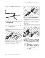
Page 23: ...g position 1 Position the roof bracket 2 Ensure the correct posi tion of the top middle and lower roof brackets 3 4 Undo the top bolt until the height of the roof bracket can be adjusted 3 Working materials SW 13 spanner Adjust the roof bracket to the height of the pantiles so that the top part of the roof bracket lies on the roofing 4 Tighten the top bolt Working materials SW 13 spanner 5 6 A B S...

Page 24: ...eight of the pantiles so that the top part lies on the roofing and the bottom part is pushed tight against the roof batten from the bottom 4 Ensure that the roof bracket fits securely around the roof batten and pantile when it engages 5 6 A Tighten the top bolt 5 Working materials SW 13 spanner Slide the pantiles into their original position again 6 To ensure that the tiles lie tightly together no...

Page 25: ...ly 4 3 4 Screw the roof bracket onto the roof batten or rafters using the three screws supplied 3 5 Slide the pantiles into their original position again 4 4 2 1 4 Installing the hanger bolt type 1 2 1 Define the clearances of the roof brackets Page 20 2 At the corresponding position drill a hole in the pantile 1 3 Tighten the hanger bolt onto the rafters through the pantile 2 3 4 Position the cen...

Page 26: ...ns Note Mounting rails and clamping elements can not be moved at the same time Installing mounting rails 2 Secure the mounting rails with the clamping elements to the roof anchors 3 Position the lower rail as far as possible downwards on the roof bracket Connecting mounting rails 4 Insert the connecting elements laterally into the mount ing rails until you feel them engage 5 Connect the mounting r...

Page 27: ...l of the collector 13 Tighten the clamping elements of the lower mounting rail Working materials SW 13 spanner Loosening the sun protection film 1 14 To ensure that the sun protection film can be easily re moved after starting up the unit loosen the sun protec tion film from the edges of the collector Removing the carrying strap 15 Remove the carrying strap Installing additional collectors 1 16 Po...

Page 28: ...ector rows 22 Install an additional collector Page 27 23 Fit the connectors Page 27 24 Tighten the clamping ring on the connection for both collectors Page 28 Positioning the top mounting rails 1 25 Slide the upper mounting rails until they are flush with the collectors 26 Ensure that the clamping block 1 of the clamping ele ments lies over the collector rails 27 Tighten the clamping elements of t...

Page 29: ...the solar circuit with hard soldered connections flat seals com pression fittings or press fittings which have been approved by the manufac turer for use in solar circuits and at cor respondingly high temperatures Caution Risk of damage to the collectors as a result of improper installation If the hydraulic connections are not in stalled properly the stainless steel tubes inside the collector may ...

Page 30: ... number 0020076776 to the collector Connect the clamping ring connection with the connec tion pipework Check the connections for tightness Insulating hydraulic connections Conditions Start up carried out 1 3 2 Insulate the hydraulic connections using the insulation 1 from installation set VTK extension set article num ber 0020076779 Cover the insulation with the cover plate 3 from installation set...

Page 31: ...ns Yes No Comments All hydraulic connections tightened Hydraulic connections routed correctly VR 11 collector sensor connected Only for systems WITH a collector sensor All clamping elements tightened Collectors connected to lightning protection device Optionally for lightning protection device Pressure testing performed Ideally with compressed air All connections tight Date Signature All installat...

Page 32: ... 32 Installation manual auroTHERM exclusive 0020077994_02 4 3 2 Disposing of the packaging The transport packaging consists largely of recyclable ma terials Observe the applicable regulations Dispose of the transport packaging properly ...

Page 33: ... installation When fitting and installing the collectors you must ob serve the chapter Safety 5 1 Preparing for fitting and installation 5 1 1 Delivery transport and positioning 5 1 1 1 Storing collectors To prevent moisture from penetrating into the collector always store the collectors dry and in a weatherproof area ...

Page 34: ... 2 rail set 2 pc 2 VTK 570 2 rail set 2 pc 3 Frame set 1 pc 4 Load plates from load plate set 4 pc 5 Hammer head bolt and nut from load plate set 2 pc 6 VTK 570 2 tube collector 1 pc 7 VTK 1140 2 tube collector 1 pc 8 Stop valve 2 way VTK for parallel connection 1 pc 9 VTK installation set basic set 1 pc 10 VTK installation set extension set 1 pc Use the image to check that the installation sets a...

Page 35: ...the collectors Ensure that the solar fluid flows through the collectors either from left to right or from right to left Conditions Number of VTK 1140 2 collectors 1 7 max 7 x VTK 1140 2 Switch up to 7 VTK 1140 2 units in series according to the 14 m aperture surface area Conditions Parallel connection aperture surface area 7 m Always connect as many collectors as possible in series even when sever...

Page 36: ...n the event of destruction of the roof skin water may penetrate the building Ensure adequate protection of the roof skin during installation on roof sealing surfaces Place large area building protection mats underneath the installation sys tem After installation check the tightness of the building shell where there are directly connected racks Commission a roofer to prepare the roof duct 5 1 5 Sel...

Page 37: ...ther using the extension set 5 1 7 Determining the ballast load floating installation Danger Risk of death and material damage due to excessive basic wind speeds The racks are designed for basic wind speeds of up to 108 km h If the basic wind speed at the site is greater than 108 km h then there can be no guarantee claim for the system Only install the rack in locations where the basic wind speed ...

Page 38: ...uroTHERM exclusive 0020077994_02 IS IE SE FI GB BE DE PL CH AT CZ HU SK SI HR BA RS RO BG MK ME TR GR AL NL PT ES FR IT NO DK BY UA MD EE RU LV LT LU AD 72 km h 81 km h 90 km h 99 km h 108 km h 108 km h 5 Use the map to determine the basic wind speed at the site ...

Page 39: ...35 407 269 30 184 38 235 45 269 up to 72 Coast and islands L L 392 259 461 307 505 345 43 259 53 307 59 338 up to 81 Inland L L 339 221 445 296 515 345 35 221 50 296 61 345 up to 81 Coast and islands L L 499 334 588 396 643 435 58 334 71 396 79 435 up to 90 Inland L L 445 296 550 370 621 419 50 296 66 370 76 419 up to 90 Coast and islands L L 586 395 691 469 762 518 71 395 86 469 96 518 up to 99 I...

Page 40: ...30 276 up to 72 Coast and islands L L 406 301 476 359 521 396 30 265 30 315 30 346 up to 81 Inland L L 352 257 495 345 531 404 30 228 30 303 30 352 up to 81 Coast and islands L L 515 391 604 464 661 510 30 341 30 404 30 443 up to 90 Inland L L 459 345 566 433 638 492 30 303 30 377 30 427 up to 90 Coast and islands L L 602 462 709 550 781 609 30 402 30 477 30 526 up to 99 Inland L L 566 433 673 521...

Page 41: ... up to 72 Coast and islands L L 365 414 430 491 474 539 43 271 54 320 62 351 up to 81 Inland L L 316 355 413 472 484 550 33 233 52 308 64 357 up to 81 Coast and islands L L 468 532 557 630 613 691 61 346 76 408 85 448 up to 90 Inland L L 413 472 519 589 590 667 52 308 70 382 82 432 up to 90 Coast and islands L L 555 628 661 744 731 822 76 407 94 481 106 531 up to 99 Inland L L 519 589 625 705 731 ...

Page 42: ...o 72 Coast and islands L L 413 234 487 279 534 307 67 234 81 279 90 307 up to 81 Inland L L 357 201 469 268 544 313 56 201 78 268 92 313 up to 81 Coast and islands L L 527 303 621 359 680 395 89 303 108 359 119 395 up to 90 Inland L L 469 268 581 335 656 380 78 268 100 335 115 380 up to 90 Coast and islands L L 619 358 731 425 806 470 107 358 129 425 144 470 up to 99 Inland L L 581 335 694 403 806...

Page 43: ... 251 up to 72 Coast and islands L L 437 270 513 321 562 354 30 241 30 286 30 314 up to 81 Inland L L 379 230 495 309 572 361 30 207 30 275 30 320 up to 81 Coast and islands L L 555 350 652 415 713 4547 30 310 30 366 30 402 up to 90 Inland L L 495 309 611 388 688 440 30 275 30 342 30 388 up to 90 Coast and islands L L 650 414 766 493 843 545 30 365 30 433 30 478 up to 99 Inland L L 611 388 727 466 ...

Page 44: ... 256 up to 72 Coast and islands L L 406 372 477 441 522 485 30 246 30 291 35 325 up to 81 Inland L L 352 319 460 424 532 494 30 212 30 280 37 325 up to 81 Coast and islands L L 516 479 607 566 664 621 35 315 45 372 52 407 up to 90 Inland L L 460 424 568 529 641 599 30 280 41 348 49 393 up to 90 Coast and islands L L 604 564 713 669 785 739 45 370 58 438 67 483 up to 99 Inland L L 568 529 677 634 7...

Page 45: ...30 45 60 C D E B F 1 B F 1 B F 1 1 1088 1106 2420 1476 3001 1749 3267 1684 2 2466 1233 1397 3 3863 4 5260 5 6657 6 8054 7 9451 1 Sun elevation of 20 winter sun Conditions Installed collectors VTK 570 2 and VTK 1140 2 in combination B D E G A C F C Define the rack clearances Quantity A 30 45 60 C D E G VTK 570 2 VTK 1140 2 B F 1 B F 1 B F 1 1 1 1776 1106 2420 1476 3001 1749 3267 1684 543 1397 1233 ...

Page 46: ...llation 46 Installation manual auroTHERM exclusive 0020077994_02 Quantity A 30 45 60 C D E G VTK 570 2 VTK 1140 2 B F 1 B F 1 B F 1 1 5 7364 1106 2420 1476 3001 1749 3267 1684 543 1397 1233 1 6 8761 1 Sun elevation of 20 winter sun ...

Page 47: ...rmine the required number of racks Specifications technical data For the first collector Two racks For each additional collector One additional rack 2 Fold out the first rack 60 45 30 3 Select the required installation angle Specifications technical data Installation angle 30 45 60 1 2 4 Push the locking button 1 on the telescopic rail 5 Pull the telescopic rail 2 into the desired installation ang...

Page 48: ...t as many racks as you need to hold the collectors Conditions Type of installation Floating installation with load plates Preparing load plates Caution Lack of tightness due to destruction of the roof skin In the event of destruction of the roof skin water may penetrate the building Ensure adequate protection of the roof skin during installation on roof sealing surfaces Place large area non slip b...

Page 49: ...ke hold of the first rack that is already secured in the installation angle Position the front rack feet above the hammer head bolt 1 When positioning the rack feet ensure that the anti rotation lock 2 engages Secure the rack feet with the self locking nut 3 Secure the rear rack feet in the same way on the other two load plates The first rack is installed so that it is stable Install the second ra...

Page 50: ...skin water may penetrate the building Ensure adequate protection of the roof skin during installation on roof sealing surfaces Place large area non slip building pro tection mats underneath the installation system If the roof is covered with gravel remove the gravel at the places where you wish to position the weights and use non slip building protection mats to protect the roof skin Define the re...

Page 51: ...he clamping blocks If a clamping block is mobile tighten the nut again 1 Install the collectors on the roof as specified in the fol lowing sections Sliding on mounting rails 1 2 3 2 Slide the two mounting rails top and bottom onto the brackets as shown in the image 3 Ensure that the open side of the bottom mounting rail is facing upwards and that the open side of the top mounting rail is facing do...

Page 52: ...ar radiation inside the units collectors can reach 300 C Avoid working in direct sunlight Cover the collectors before starting work You should preferably perform the work in the morning Wear suitable safety gloves 13 Place the collector so that its lower edge is in the pro file of the mounting rail 1 upper collector Ensure that the mounting rail 1 surrounds the lower edge of the collector Securing...

Page 53: ... article number 0020076779 in the thread of the second collector B with the cap nut of the first collector 1 and 2 22 Push the collectors together Tightening the clamping ring connection Caution Risk of damage to the collectors as a result of improper installation If the hydraulic connections are not in stalled properly the stainless steel tubes inside the collector may become damaged When tighten...

Page 54: ...l tubes inside the collector may become damaged When tightening the clamping ring con nection hold a second spanner against it 1 Connect the collector flow and return to the system with the connection tubes 2 To do this connect the clamping ring connection from the installation set VTK basic set article number 0020076776 to the collector 3 Connect the clamping ring connection with the connec tion ...

Page 55: ...ations All bolts securely tightened Installation and telescopic rail Adequate ballast weights used Only for floating installation Load weights adequately secured against slipping and tilting Only for floating installation Rack anchored and bolts tightened Only for direct connection All hydraulic connections tightened Hydraulic connections routed correctly VR 11 collector sensor connected Only for ...

Page 56: ...n 56 Installation manual auroTHERM exclusive 0020077994_02 5 3 2 Disposing of the packaging The transport packaging consists largely of recyclable ma terials Observe the applicable regulations Dispose of the transport packaging properly ...

Page 57: ...and cause material damage and personal injury Instruct the operator to observe the specified maintenance intervals strictly Perform maintenance work on the col lectors in accordance with the mainten ance plan 6 3 General inspection and maintenance instructions Danger Risk of death injury and material dam age due to improper maintenance and repairs Improper maintenance work or repairs can impair th...

Page 58: ...er clean the collectors with a high pressure cleaner Caution Material damage due to cleaning agent Cleaning agents may damage the surface structure of the collector and decrease its efficiency Never clean the collector with cleaning agents Clean the collectors with a sponge and water 6 7 Checking brackets and collector components for firm seating Check the firm seating of all threaded connections ...

Page 59: ...structions 7 2 2 Disposing of defective collectors Your Vaillant collector consists largely of recyclable materi als The Vaillant collector must not be disposed of with normal household waste Observe the applicable regulations Dispose of defective Vaillant collectors properly 7 2 3 Sealing leaking connections Danger Risk of burns and scalding In the event of solar radiation inside the units collec...

Page 60: ...ant replacement tubes article number 0020077347 Note If a tube has been damaged by a hailstorm for example the individual tube can be re placed The solar plant can remain in operation when replacing the tube 2 Observe the relevant installation manual that is en closed with the replacement tube 7 2 7 Disposing of defective tubes The Vaillant tubes consist largely of recyclable materials The Vaillan...

Page 61: ...emporarily de commission the solar plant To do this you must switch off the solar pump Temporarily decommission the solar plant as described in the operating system instructions 8 2 Permanently decommissioning 8 2 1 Removing collectors Danger Risk of burns and scalding In the event of solar radiation inside the units collectors can reach 300 C Avoid working in direct sunlight Cover the collectors ...

Page 62: ...r fluid 8 2 2 Recycling and disposal Your Vaillant collector consists largely of recyclable materi als Observe the applicable regulations Disposing of collectors You must not dispose of your Vaillant collector or any of its accessories in normal domestic waste Dispose of the old unit and any accessories properly Disposing of solar fluid The solar fluid must not be disposed of with normal house hol...

Page 63: ...on manual 63 9 Customer service Vaillant Service Applies to Great Britain To ensure regular servicing it is strongly recommended that arrangements are made for a Maintenance Agreement Please contact Vaillant Service Solutions for further details 44 80 70 606 07 77 ...

Page 64: ...t Epsilon absorber emission 6 see also ITW test report Grid dimensions length x height x depth m 0 7 x 1 65 x 0 11 1 39 x 1 65 x 0 11 Gross area m 1 16 2 30 Aperture surface area m 1 0 2 0 Absorber surface area m 1 0 2 0 Collector capacity l 0 9 1 8 Weight kg 19 37 System overpressure max permissible bar 10 Shutdown temperature max C 272 Connection width flow return mm 15 Material for the tube col...

Page 65: ...Technical data 10 0020077994_02 auroTHERM exclusive Installation manual 65 10 2 Dimensions 1652 111 702 ...

Page 66: ...077994_02 1652 111 1392 10 3 Efficiency and pressure loss Efficiency of the VTK 570 2 and the VTK 1140 2 at a solar energy input EG of 300 W m2 0 0 10 20 30 40 50 60 70 80 5 10 15 20 25 30 35 40 45 50 55 60 65 70 75 80 ΔT η η Efficiency ΔΤ Τcollector ambient air Τ K ...

Page 67: ...2 at a solar energy input EG of 800 W m2 0 0 10 20 30 40 50 60 70 80 5 10 15 20 25 30 35 40 45 50 55 60 65 70 75 80 ΔT η η Efficiency ΔΤ Τcollector ambient air Τ K Pressure loss 160 140 120 100 90 60 40 20 0 Q l h Δp mbar 0 50 100 150 200 250 300 350 400 450 500 VTK 1140 2 VTK 570 2 Q Mass flow l h Δp Pressure loss mbar ...

Page 68: ...mer service 63 D Decommissioning 61 Disposal Collectors 62 Packaging 32 56 Solar fluid 62 Documents other applicable 5 F Final work Installing 31 55 H Hydraulic connections Installing 29 54 I Identification plate 10 Installation clearances Complying with 14 35 Installing Checking 31 55 Intended use 8 L Leaking connections Sealing 59 M Maintenance Preparing 57 Maintenance plan 57 P Packaging Dispos...

Page 69: ...ERM exclusive Installation manual 69 Spare parts Maintenance 57 Troubleshooting 59 T Technical data 64 Dimensions 65 Efficiency 66 Pressure loss 66 Tubes Disposal 60 Replacing 59 Type overview 10 U Unit Purpose 10 Use intended 8 ...

Page 70: ......

Page 71: ......

Page 72: ...0020077994_02 ...

Reviews: