Installation 5
0020233500_01 auroCOMPACT Installation and maintenance instructions
15
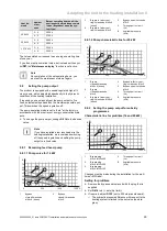
≥ 4%
H
L1
L2
L3
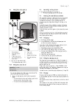
The total length of the piping between the solar collectors
and the cylinder must not exceed the specified values.
▶
If the installation reaches a height of 12 metres, install a
back-up pump.
▶
Observe the information in the table below.
–
L = L1 + L2 + L3
Length of the 2 in 1 solar tube (L)
Building height (H)
8 m
12 m
150L
One sensor
Without re-
tention ves-
sel (access-
ory)
20 m
20 m
Two
sensors
Without re-
tention ves-
sel (access-
ory)
12.5 m
–
With reten-
tion vessel
(accessory)
20 m
20 m
190L
One sensor
Without re-
tention ves-
sel (access-
ory)
20 m
20 m
Two
sensors
Without re-
tention ves-
sel (access-
ory)
20 m
15 m
With reten-
tion vessel
(accessory)
–
20 m
Three
sensors
With reten-
tion vessel
(accessory)
20 m
20 m
Note
If there is insufficient solar fluid in the installa-
tion, the pump may cause a noise. If required,
fill the unit.
5.5.4
Solar connection
Note
The unit has the following components as stand-
ard:
- Solar pump
- Safety assembly
- Fill level indicator
- Solar fluid collecting vessel
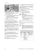
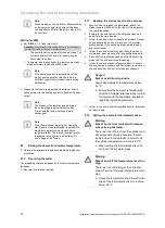
1
2
1
Solar return connection
(from the collector), G
3/4
2
Solar flow connection
(to the collector), G 3/4
1.
Consult the installation instructions for the solar system
when setting up the hydraulic connection.
2.
Connect the enclosed solar connections to solar tube 2
at position 1.
3.
Connect the solar circuit's flow and return pipes to the
floor-standing boiler.
5.6
Air/flue system
5.6.1
Installing the air/flue pipe
▶
Install the air/flue pipe as described in the separate set-
up instructions for the air/flue pipe.
5.6.2
Changing the connector for the air/flue pipe
Note
The products are fitted with a 60/100 mm dia-
meter connector as standard.


