Operation 6
0020233500_01 auroCOMPACT Installation and maintenance instructions
19
Conditions
: If you are connecting a safety thermostat for underfloor heat-
ing:
▶
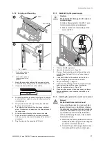
Connect the thermostat to the
Burner off
plug instead of
the shunt.
3.
Close the electronics box.
4.
To trigger the
Comfort
pump operating mode (pump
runs permanently) using a multi-circuit controller,
change the diagnostics code D.018 Pump operat-
ing mode (
→
Page 28) from
Eco (3)
(pump runs
intermittently) to
Comfort (1)
.
5.7.8
Connecting additional components
The following components can be actuated:
–
Hot water circulation pump
–
External heating pump
–
Cylinder charging pump (not activated)
–
Extractor hood
–
External solenoid valve
–
External fault signal
–
Solar pump (not active)
–
eBUS remote control (not active)
–
Legionella protection pump (not active)
–
Solar valve (not active).
5.7.8.1 Using the auxiliary relay
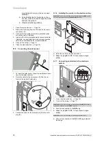
1.
Connect an additional component directly to the integ-
rated auxiliary relay using the grey plug on the PCB.
2.
Connect the wiring in the same way as described in the
section "Installing the control (
→
Page 18)".
3.
To start up the connected component, select the com-
ponent using diagnostics code
D.026
, see Calling up
diagnostics codes (
→
Page 27).
5.7.8.2 Using the VR 40 ("2 in 7" multi-functional
module)
1.
Install the components in accordance with the respect-
ive instructions.
2.
Select
D.027
(
→
Page 27) to actuate relay 1 on the
multi-functional module.
3.
Select
D.028
(
→
Page 27) to actuate relay 2 on the
multi-functional module.
5.7.8.3 Actuating the circulation pump according to
requirements
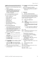
1.
Connect the connection cable for the external button
using terminals 1
(0) and 6 (functional drawing) on
the X41 edge connector, which is supplied with the con-
troller.
2.
Plug the edge connector into the PCB slot X41.
3.
Press the external button to make the circulation pump
to run for five minutes.
5.7.8.4 Actuating a circulation pump with an eBUS
controller
1.
Select a hot water programme (preparation).
2.
Parametrise a circulation programme on the controller.
◁
The pump runs during the time period specified in
the programme.
6
Operation
6.1
Operating concept of the product
The operating concept and the display and setting options of
the end user level are described in the operating instructions.
An overview of the display and setting options of the installer
level can be found in the section "Overview of the menu
structure
–
Installer level" (
→
Page 43).
6.1.1
Calling up the installer level
Caution.
Risk of material damage caused by incor-
rect handling.
Incorrect settings at installer level may cause
damage and operating faults to the heating
installation.
▶
You must only access the installer level if
you are an approved competent person.
Note
The installer level is protected against unauthor-
ised access using a password.
1.
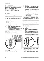
Press
and
("i") simultaneously.
◁
The following menu appears in the display.
2.
Use the
or
button to scroll until the
Installer
level
menu point appears.
3.
Press (
OK
) to confirm your selection.
◁
In the display, the text
Enter code
appears along
with the value
00
.
4.
Use
or
to set the value
17
(code).
5.
Press (
OK
) to confirm your selection.
◁
The installer level appears with a selection of menu
points.
6.2
Live Monitor (status codes)
Menu
→
Live Monitor
Status codes in the display provide information on the pro-
duct's current operating status.
Status codes
–
Overview
Status codes
–
Overview (
→
Page 49)


