background image

Split Type Installation Manual

4

4  Declaration of Conformity

The manufacturer declares that this unit has been 
designed and constructed in compliance with the 
standard in force with regard to obtaining the CE 
Marking.

Description of the Unit

This unit is comprised of the following elements:
-  Indoor unit.
-  Outdoor unit.
-  Remote controller.
-  Connections and accessories.

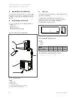
Figure 5.1 shows the unit components.

Fig. 5.1   Unit components.

Legend

1  Indoor Unit
2  Outdoor Unit
3  Remote controller
4  Interconnecting pipework (not supplied)
5  Condensed water drainage pipe

5.1 

Indoor Unit

The indoor unit heats and cools air to be supplied to the 
room to be conditioned.

The dimensions and weights of the indoor unit are 
shown on Figure 5.2 and Table 5.1, depending on the 
model (please consult the model nameplate).
The dimensions are given in mm.

Fig. 5.2   Dimensions of the indoor unit.

Legend

H  Height
L  Length
D  Depth

MODEL

H

L

D

kg

VAI 2-025 WNI

265

790

200

8,5

VAI 2-035 WNI

265

790

200

8,5

Table 5.1 Dimensions and weights of the indoor unit.

4 Declaration of Conformity
5 Description of the Unit 

Summary of Contents for climaVAIR VAM 2-050 W2N

Page 1: ...VAM 2 050 W2N VAM 2 060 W2N VAM 2 085 W3N VAM 2 110 W4N climaVAIR DE EN HR IT TR...

Page 2: ......

Page 3: ...For the fitter VAM 2 050 W2N VAM 2 060 W2N VAM 2 085 W3N VAM 2 110 W4N Installation Manual Air conditioner climaVAIR Split Type EN...

Page 4: ...n of the Pipe Work 10 9 3 1 Correct Removal of the Condensate Water 10 9 3 2 Handling the Refrigerant Pipes 10 9 3 3 Correct installation of the condensate pipe work 11 9 3 4 Making Holes for the Pipe...

Page 5: ...f maintenance operations involving the handling of the refrigerant fluid must have the necessary certification to comply with all local and international regulations 2 Extreme Operating Conditions Thi...

Page 6: ...or Unit 2 Outdoor Unit 3 Remote controller 4 Interconnecting pipework not supplied 5 Condensed water drainage pipe 5 1 Indoor Unit The indoor unit heats and cools air to be supplied to the room to be...

Page 7: ...onsult the model nameplate The dimensions are given in mm Fig 5 3 Dimensions of the outdoor unit Legend H Height L Length D Depth A Length of valves B Distance between valves C Distance from the secon...

Page 8: ...outdoor and indoor unit they allow the water to be properly discharged which condenses during the normal operation of the unit Electric connections these supply electric energy to the unit 5 5 Suppli...

Page 9: ...38 26 32 38 26 32 38 Sound Pressure level 2 dB A 26 32 38 28 35 40 26 32 38 26 32 38 Sound Pressure level 3 dB A 28 35 40 26 32 38 Sound Pressure level 4 dB A 28 35 40 Outdoor Unit Air Flow volume m3...

Page 10: ...s in force Do not dispose of packaging irresponsibly recycle where possible 8 Installation 8 1 Qualification of the Installation Personnel Ensure that this unit is installed by suitable qualified pers...

Page 11: ...clearances are met Choose a position site that will allow air to reach all parts of the room evenly Avoid beams obstructions or lights which would interfere with the airflow Install the indoor unit a...

Page 12: ...to refrigerant pipes through the use of unsuitable materials Use only pipes specifically intended for refrigeration and R410A refrigerant Note In specialised dealers you will find refrigerant pipes a...

Page 13: ...pipe with a rising bend see Figure 9 2 Fig 9 2 Avoid rising bends If the drain is run to a tank or butt avoid installing the condensed water pipe with it free end submerged in water see Figure 9 3 Fi...

Page 14: ...pipes Carefully bend the installation pipe in the right direction taking care not to overbend or kink the pipe Warning Danger of breakdowns or malfunction Danger of damage to the coolant pipes Bend th...

Page 15: ...sure that the pipework is not trapped behind the unit 10 Installation of the Outdoor Unit 10 1 Selecting the Assembly Location Warning Outdoor units must be placed in accessible areas for subsequent m...

Page 16: ...breaks Cut the pipes leaving enough extra piping hanging over to enable the unit to be connected at the outdoor unit joins Flare the refrigerant pipe after first placing the flare nut on the pipe Joi...

Page 17: ...ocal electrical sockets only use with a suitable adaptor or replace the plug with a UK style one Danger Danger of electric shock Use wiring in accordance with the respective local national and interna...

Page 18: ...Danger of breakdowns or malfunction If the fuse on the PC board is blown please change it with type T 3 15A 250V Open the front panel of the indoor unit by pulling it upwards Remove the wiring cover o...

Page 19: ...Warning Danger of malfunction and breakdowns resulting from water penetration Always terminate the interconnecting cable from below the cable entry to avoid water penetration into the terminal box War...

Page 20: ...up to 25 meter in mm2 2 5 2 5 4 6 Indoor Outdoor Outdoor Outdoor Outdoor Outdoor Thermal magnetic circuit breaker type D A 16 16 20 25 Interconnection section up to 25 meter mm2 These units already in...

Page 21: ...efrigerant circuit must be periodically checked for leakage Take the necessary actions to ensure these tests are performed and the results correctly logged into the maintenance record of the machine T...

Page 22: ...checking for leaks Warning Danger of malfunction and leaks Ensure that the service valves on the outdoor unit are closed 12 3 Start Up Fig 12 5 Filling the installation Legend 1 Two way valve 2 Actuat...

Page 23: ...igerant from the system You will need the correct refrigerant recovery unit and refrigerant reclaim cylinder to achieve this Warning Never release refrigerant into the environment Refrigerant R410A is...

Page 24: ...ion for Multi OUTDOOR UNIT DISPLAY LED STATUS E0 EEPROM error E1 N 1 Indoor units pipe temp sensor or connector of pipe temp sensor is defective E2 N 2 Indoor units pipe temp sensor or connector of pi...

Reviews: