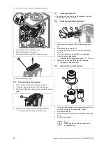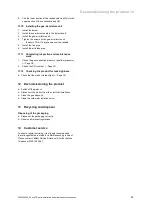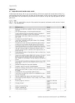
Start-up 7
0020230535_05 ecoFIT pure Installation and maintenance instructions
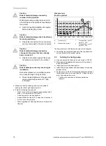
17
–
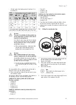
if the pH value of the heating water is less than 6.5 or
more than 8.5.
Total
heating
output
Water hardness at specific system volume
1)
≤
20 l/kW
> 20 l/kW
≤
50 l/kW
> 50 l/kW
kW
ppm
CaCO
₃
mol/
m
³
ppm
CaCO
₃
mol/
m
³
ppm
CaCO
₃
mol/
m
³
< 50
< 300
< 3
200
2
2
0.02
> 50
to
≤
200
200
2
150
1.5
2
0.02
> 200
to
≤
600
150
1.5
2
0.02
2
0.02
> 600
2
0.02
2
0.02
2
0.02
1) Nominal capacity in litres/heating output; in the case of multi-
boiler systems, the smallest single heating output is to be used.
Caution.
The use of unsuitable heating water may
cause aluminium corrosion and a result-
ing lack of leak-tightness.
In contrast to steel, grey cast iron or copper,
for example, aluminium reacts with alkaline
heating water (pH value > 8.5) to produce
substantial corrosion.
▶
When using aluminium, make sure that
the pH value of the heating water is
between 6.5 and a maximum of 8.5.
Caution.
Risk of material damage if the heating
water is treated with unsuitable additives.
Unsuitable additives may cause changes in
the components, noises in heating mode and
possibly subsequent damage.
▶
Do not use any unsuitable frost and cor-
rosion protection agents, biocides or seal-
ants.
No incompatibility with our products has been detected to
date with proper use of the following additives.
▶
When using additives, follow the manufacturer's instruc-
tions without exception.
We accept no liability for the compatibility of any additive or
its effectiveness in the rest of the heating system.
Additives for cleaning measures (subsequent
flushing required)
–
Adey MC3+
–
Adey MC5
–
Fernox F3
–
Sentinel X 300
–
Sentinel X 400
Additives intended to remain permanently in the
installation
–
Adey MC1+
–
Fernox F1
–
Fernox F2
–
Sentinel X 100
–
Sentinel X 200
Additives for frost protection intended to remain
permanently in the installation
–
Adey MC ZERO
–
Fernox Antifreeze Alphi 11
–
Sentinel X 500
▶
If you have used the above-mentioned additives, inform
the end user about the measures that are required.
▶
Inform the end user about the measures required for frost
protection.
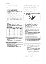
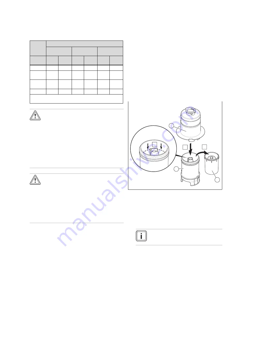
7.4
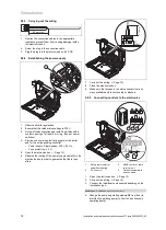
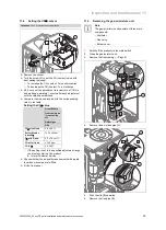
Filling the condensate trap
C
2
3
1
A
B
1.
Unclip the lower section of the condensate trap
(1)
from
the upper section of the condensate trap
(2)
.
2.
Remove the float
(3)
.
3.
Fill the lower section of the condensate trap with water
up to 10 mm below the upper edge of the condensate
discharge pipe.
4.
Re-insert the float
(3)
.
Note
Check whether the float is present in the
condensate trap.
5.
Clip the lower section of the condensate trap
(1)
into the
upper section of the condensate trap
(2)
.

