Instructions for Use, Installation and Servicing ecoMAX pro
19
Electrical connections 11
11.2 Electrical connections – testing
Carry out preliminary electrical system checks as below:
1.
Test insulation resistance to earth of mains cable.
2.
Test the earth continuity and short circuit of cables.
3.
Test the polarity of the mains.
When completed ensure the supply to the boiler is isolated.
Danger!
This appliance must be earthed.
All system components must be of an approved type,
and meet the requirements of the current IEE Wiring
Regulations, and in IE the current edition of the ETCI
rules. Electrical components have been tested to meet
the equivalent requirement of the BEAB.
Connection of the whole electrical supply must be
through a common isolator.
Isolation should preferably be by a double pole switched
fused spur box having a minimum contact separation
of 3mm on each pole. The fused spur box should be
readily accessible and preferably adjacent to the boiler.
It should be identified as to its use. A fused three pin
plug and shuttered socket outlet may be used instead of
a fused spur box provided that:
a) They are not used in a room containing a fixed bath or
shower.
b) Both the plug and socket comply with the current
issue of BS1363.
Do not interrupt the mains supply with a time switch or
programmer.
Caution!
This appliance must be wired in accordance
with these instructions. Any fault arising from
incorrect wiring cannot be put right under the
terms of the Vaillant guarantee.
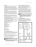
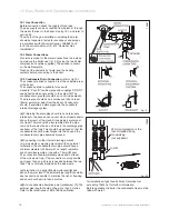
11.1 Appliance, pump and external controls.
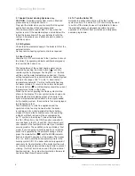
ecoMAX pro boilers are fitted with a terminal box located
at the base of the boiler into which all connections are
made. To gain access to the terminal box, remove the
two retaining screws indicated in fig 11.1 and carefully
lower to reveal the terminal strip inside.
Disconnect and remove the test cable from the terminal
strip and discard.
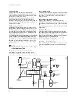
Connect both the mains supply and switched live from
the external controls (room thermostat and, if applicable,
frost thermostat) into the marked terminals as shown in
figs 11.2 and 16.3.
Connect the pump supply into the marked pump
terminals as shown in figs 11.2 and 16.3.
Note!
The boiler incorporates a pump overrun
thermostat. Only feed the pump from the
marked terminals in the terminal box on the
boiler, not from a separate supply.
Observe all terminal markings and colour codes shown
in fig 11.2.
Ensure that all flexible cords are routed through the
strain relief cable glands on the inlet of the terminal box.
Refit the terminal box to the underside of the boiler using
the two retaining screws.
Fig 11.1
12953
Fig 11.2
CONNECTION
BOX
RETAINING
SCREWS (2)
131
13
Summary of Contents for ecoMAX pro 18E
Page 37: ...Instructions for Use Installation and Servicing ecoMAX pro 37 Declaration of Conformity 17...
Page 38: ...Instructions for Use Installation and Servicing ecoMAX pro 38...
Page 39: ...Instructions for Use Installation and Servicing ecoMAX pro 39...
Page 40: ...0020005557_04 GB 08 2006 Subject to alteration...

