Instructions for Use, Installation and Servicing ecoMAX pro
15
7 Flue
8 Installation preparation
1)
In addition, the terminal should not be nearer than 150mm to an opening
in the building fabric formed for the purpose of accommodating a built-in
element such as a window.
2)
Dimension B,C and D; These clearances may be reduced to
25 mm without affecting the performance of the boiler. In order to ensure
that the condensate plume does not affect adjacent surfaces the terminal
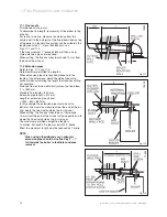
should be extended as shown in Fig 7.4.
3)
Dimension F; This clearance may be reduced to 25 mm without affecting
the performance of the boiler. However, in order to ensure that the con-
densate plume does not affect adjacent surfaces a clearance of 300 mm is
preferred.
4)
BS 5440-1 It is recommended that a fanned flue terminal should be posi-
tioned as follows:
a) at least 2m from an opening in a building directly opposite, and
b) so that the products of combustion are not directly directed to discharge
across a boundary. For IE, recommendations are given in the current edition
of IS 813.
TERMINAL POSITION
mm
A
1)
Directly below an opening, above an opening
or horizontal to an opening i.e. air brick, opening
window or other, etc
300
B Below gutters, soil pipes or drain pipes
75
2)
C Below eaves
200
2)
D Below balconies
200
2)
E From vertical drain pipes and soil pipes
25
F From internal or external corners
300
3)
G Above ground, roof or balcony
300
H From a surface facing a terminal
600
4)
I
From a terminal facing a terminal
1200
K Vertically from a terminal on the same wall
1500
L Horizontally from a terminal on the same wall
300
M Distance from adjacent wall for vertical Flue
500
balcony/eaves
flue extended to
clear any overhang
flue adequately
supported
gutter
7.3 Internal Flue Installation
The flue can be installed from inside the building when
access to the outside wall face is not practicable.
7.4 Flue Options
There are various flue systems to choose from, as
follows:
• Vertical air/flue duct and terminal
303 900
• Air/flue duct extension (470 mm)
303 902
• Air/flue duct extension (970 mm)
303 903
• Air/flue duct extension (1970 mm)
303 905
• Telescopic air/flue duct extension
(440 mm - 690 mm)
303 906
• 87° elbow
303 910
• Two 45° bends
303 911
• Standard horizontal air/flue duct
with elbow and terminal (800 mm)
303 930
Additional accessories are available.
8 Installation preparation
8.1 Unpacking of Boiler
Stand the boiler carton upright.
Cut and remove the securing straps and lift off the carton
sleeve. Place aside the flue adaptor and connections
pack until required.
Carefully lay the boiler on its back, remove the two front
casing panel securing screws and lift off the panel from
two retaining lugs, see diagram 8.1.
Remove the two inner casing panel securing screws
at the bottom front of the panel, then lift off the two
retaining lugs, see diagram 8.2.
8.2 Using boiler template
Fix the paper template to the wall ensure that the
template is vertical.
The template shows
• The position of the fixing holes for the boiler mounting
bracket (1).
• The position of the connections.
• The position of the flue exit hole.
Mark the position of the top hanging bracket fixing holes.
Drill 2 holes to accept the wallplugs/screws supplied for
the hanging bracket.
NOTE:
Use alternative fixing holes where necessary.
Fig 7.4
12677
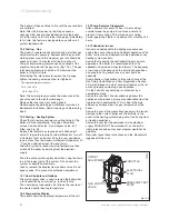
Fig 8.1
12678


