40
90
0
210
95
0
215
100
0
220
> 100 to
not
< 170 mm
possible
170
100
290
175
108
295
180
115
300
185
122
305
190
129
310
195
136
315
200
143
320
205
150
325
210
157
330
215
164
335
220
171
340
225
178
345
230
185
350
235
192
355
240
199
360
245
207
365
250
214
370
255
221
375
260
228
380
265
235
385
270
242
390
275
249
395
280
256
400
285
263
405
290
270
410
295
277
415
300
284
420
305
291
425
310
298
430
315
306
435
320
313
440
325
320
445
330
327
450
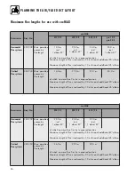
FITTING AIR/FLUE DUCT EXTENSIONS
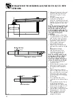
Offset
Length of
Height
[in mm]
air conduit
[in mm]
[in mm]
Offset
Length of
Height
[in mm]
air conduit
[in mm]
[in mm]
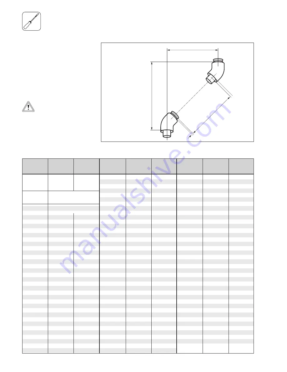
Table 11.2: Length of surplus with 45° bends
Offset
Length of
Height
[in mm]
air conduit
[in mm]
[in mm]
Height
Offset
Lenght of air conduit
10
10
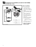
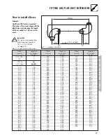
How to install elbows
Example:
An offset of 400 mm is measured.
This value is then used, along with the
table below, to determine the length
of the air conduit (= 284 mm) and the
height (= 420 mm).
Important:
This gives a corresponding
exhaust-conduit length of
284 + 40 = 324 mm.
(cf. page 41)
GU_LAZ 103/2GB
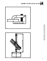
Fig. 11.2: Installation of 45° bends
335
334
455
340
341
460
345
348
465
350
355
470
355
362
475
360
369
480
365
376
485
370
383
490
375
390
495
380
397
500
385
405
505
390
412
510
395
419
515
400
426
520
405
433
525
410
440
530
415
447
535
420
454
540
425
461
545
430
468
550
435
475
555
440
482
560
445
489
565
450
496
570
455
504
575
460
511
580
465
518
585
470
525
590
475
532
595
480
539
600
485
546
605
490
553
610
495
560
615
500
567
620
505
574
625
510
581
630
515
588
635
520
596
640
525
603
645
530
610
650
535
617
655
540
624
660
545
631
665
550
638
670
555
645
675
560
652
680
565
659
685
570
666
690
575
673
695
580
680
700
585
687
705
590
695
710
595
702
715
600
709
720
605
716
725
610
723
730
615
730
735
620
737
740
625
744
745
630
751
750
635
758
755
640
765
760
645
772
765
650
779
770
655
786
775
660
794
780
665
801
785
670
808
790
675
815
795
680
822
800
685
829
805
690
836
810
695
843
815
700
850
820
705
857
825
710
864
830
715
871
835
720
878
840

