Installation 4
0020134823_04 ecoTEC plus Installation and maintenance instructions
9
4.3
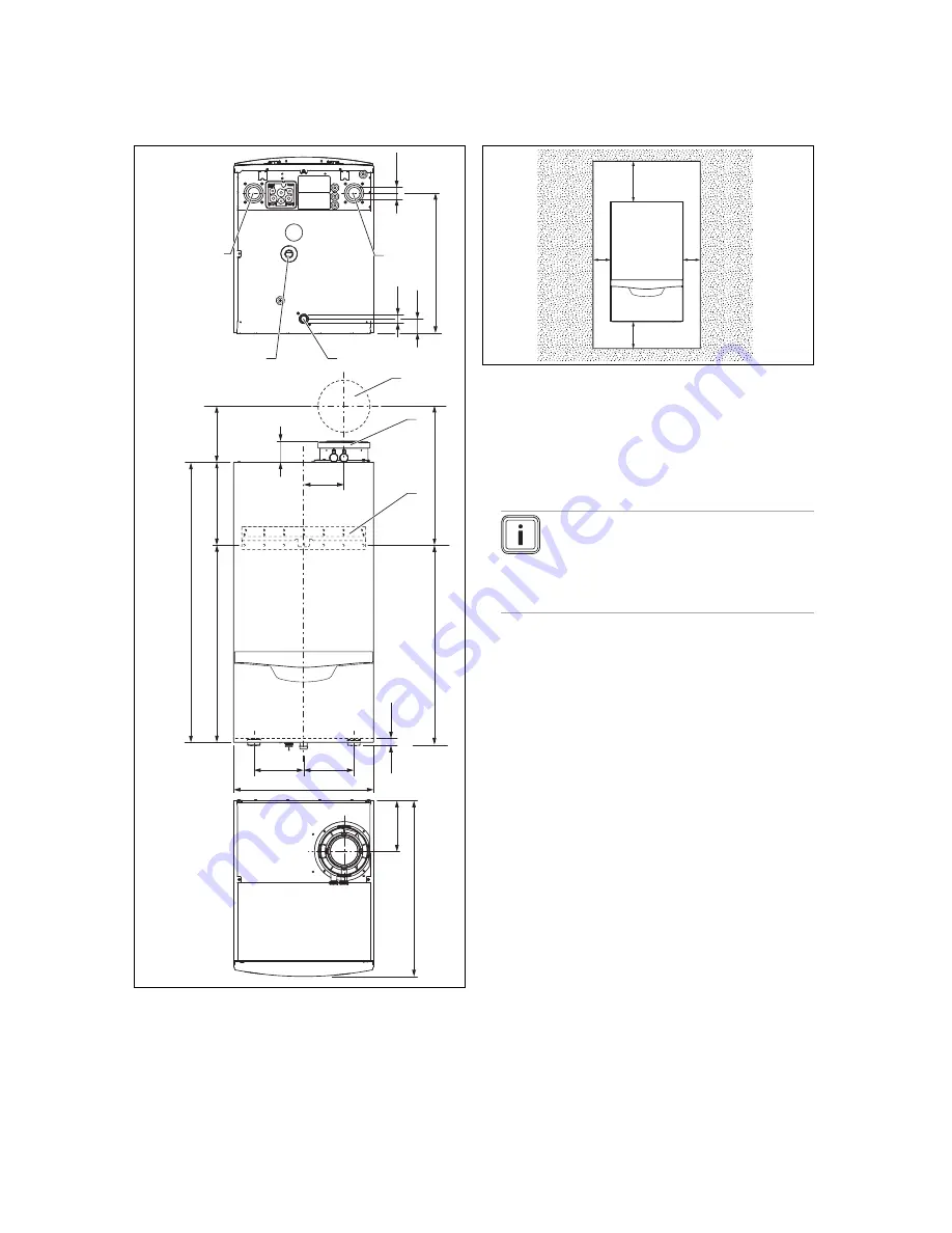
Product dimensions and connection
dimensions
28
7
190
67
3
60
3
480
17
5
138
172
172
70
22
48
2
Ø2
5
49
G 1 1/
4
96
0
47
7
680
,5
1
2
3
4
5
6
7
1
Wall duct for flue pipe
2
Flue pipe connection
3
Hanging bracket
4
Heating flow
5
Condensate trap con-
nection
6
Gas connection
7
Heating return
4.4
Minimum clearances and installation
clearances
C
C
A
B
A
350 mm (110/160 mm
diameter flue pipe)
At least 450 mm for
cascade design
B
400 mm
C
Optional approx. 200
mm
D
Clearance of 600 mm
in front of the product
for easy access during
maintenance work
▶
When using the accessories, observe the minimum clear-
ances/installation clearances.
Note
A lateral clearance is not required, however
you can also remove the side sections if there
is sufficient space at the side (approx. 200
mm) in order to facilitate maintenance or re-
pair work.
▶
Where units are installed in cascade, observe the gradi-
ent of the flue pipe (approx. 50 mm/m).
4.5
Clearance from combustible components
It is not necessary to ensure that there is a clearance
between the product and combustible components, as the
temperature of the product will never exceed the maximum
permissible temperature of 85 °C at its nominal heat output.
The same applies to the external air guiding of the concentric
flue pipe.
4.6
Using the installation template
1.
Position the installation template vertically over the in-
stallation site.
2.
Secure the template to the wall.
3.
Mark on the wall all the points required for your installa-
tion.
4.
Remove the installation template from the wall.
5.
Drill all the holes required.
6.
Make any perforations necessary.


