6
Installation instructions 0020197272_02
Line length
Sensor lines
≤
50 m
Bus lines
≤
125 m
4.3
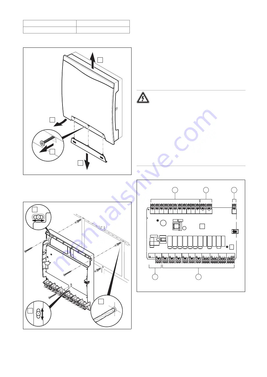
Removing the front casing
A
C
D
B
▶
Remove the front casing in accordance with the illustra-
tion.
4.4
Installing the wall base
B
B
A
▶
Install the wall base using the appropriate fastening ma-
terial in accordance with the illustration.
4.5
Installing the front casing
1.
Mount the front casing at the top of the wall socket.
2.
Use the fixing screw to secure the front casing.
3.
Slide the cover over the fixing screw until the cover
clicks into place.
5
Electrical installation
Only qualified electricians may carry out the electrical install-
ation.
5.1
Carrying out the wiring
Danger!
Risk of electric shock
There is a risk of electric shock when working
on electrical components that are connected
to the low-voltage network.
▶
Disconnect the product from the power
supply.
▶
Secure the product against being
switched back on again.
▶
Check that the product is voltage-free.
▶
Only open the product when it is voltage-
free.
1.
Remove the front casing. (
BUS
- +
S1
1 2
S2
1 2
S3
1 2
S4
1 2
S5
1 2
S6
1 2
S7
1 2
S8
1 2
S9
1 2
S10
1 2
S11
1 2
S12
O
I
S13
O
I
R7/8
N 1 2
R13
N
N
R11/12
N 1 2
R9/10
N 1 2
R6
L
N
R5
L
N
R4
L
N
R3
L
N
R2
L
N
R1
L
N
230V
L
N
230V
L
N
1
4
5
2
3
1
Input
2
Input and output
3
eBUS
4
Output
5
Mains connection
2.
Connect the required inputs and outputs from the se-
lected basic system diagram.
3.
Connect the product using a fixed connection and a
partition with a contact gap of at least 3 mm (e.g. fuses
or power switches).
Summary of Contents for FM5
Page 1: ...en Installation instructions FM5 functional module VR 71 0020197272_02 12 10 2022...
Page 9: ......
Page 10: ......
Page 11: ......


