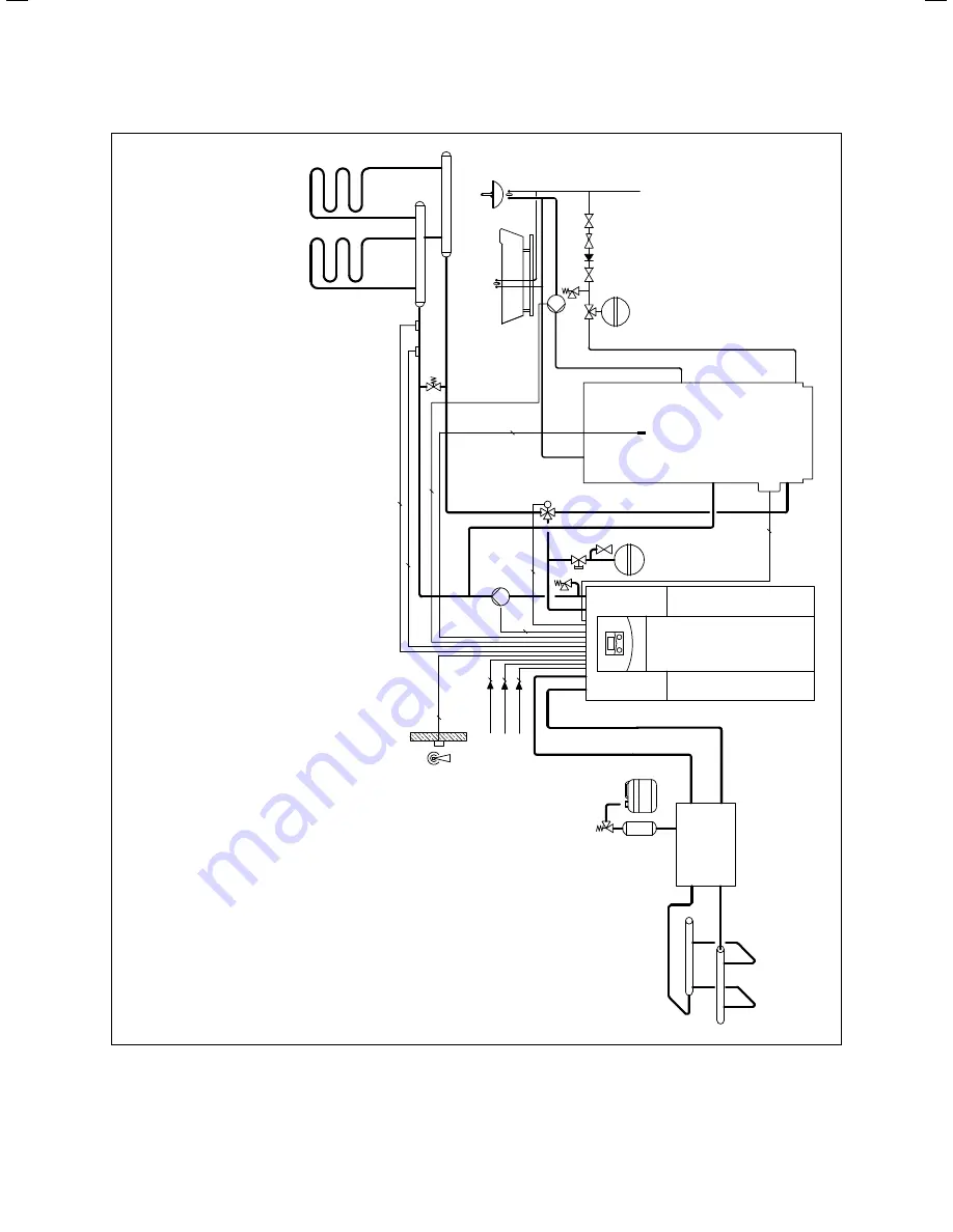
Hydraulics installation
Installation instructions geoTHERM 0020051574_04
29
5
42
a
42
a
57
65
56
2
3
3
43
19
HKP
VF2
42
c
ZP
42
a
SP
5
LP
/UV1
16
2
3
0 V~
3
3
3
400 V~
400 V~
5
2
400 V~
5
3
4
ZH
3
13
42
b
32
58
M
50
3
geoTHERM he
at pump VW
S ..
0
/2
5
Dome
s
tic hot w
at
er c
ylinder
13
W
e
ather-c
ontr
olled ener
gy b
alanc
e c
ontr
oller
16
VR
C
-DCF r
ec
eiv
er with out
side t
emper
at
ur
e s
ens
or
19
Maximum thermo
s
tat
3
2
C
apped s
top v
alv
e
4
2a
Exp
ansion r
elief v
alv
e
4
2b
He
ating cir
cuit diaphr
agm e
xp
ansion t
ank
Hot w
at
er diaphr
agm e
xp
ansion t
ank
43
S
af
e
ty gr
oup
, w
at
er c
onnection
50
B
y
-p
as
s v
alv
e
56
He
at pump
s f
or brine filling unit
5
7
Brine e
xp
ansion t
ank
5
8
Filling and dr
ainage t
ap
6
5
Brine c
ollecting t
ank
HKP
He
ating cir
cuit pump
SP
C
ylinder t
emper
at
ur
e s
ens
or
ZP
Cir
culation pump
Ke
y
42
c
LP
/UV1
He
ating/
c
ylinder char
ging div
er
ter v
alv
e
ZH
Electric auxiliary he
at
er
VF2
Flo
w t
emper
at
ur
e s
ens
or
5.4
Sample hydraulic scheme: The direct heating mode and
DHW tank


