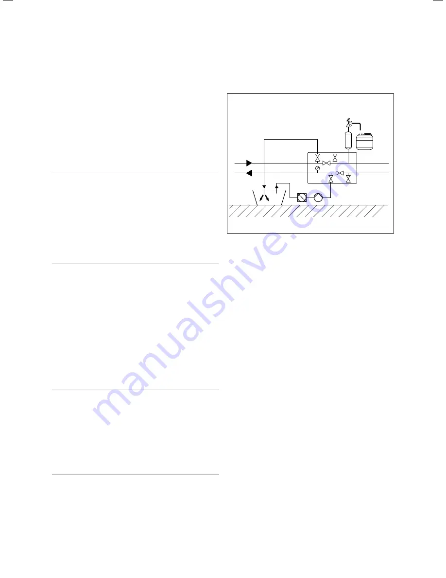
Filling the heating and heat source circuit
40
Installation instructions geoTHERM 0020051574_04
6
The brine fluid consists of water mixed with a heat transfer
fluid concentrate. We recommend that you add propylene
glycol (alternatively: ethylene glycol) with corrosion-inhibit-
ing additives.
The brine fluids that may be used differ greatly from region
to region. Please find out about this from the authorities
responsible.
Only the following brine fluids are authorised by Vaillant for
operation of the heat pump:
– Aqueous solution with 30 %
±
1 % vol. ethylene glycol
– Aqueous solution with 33 %
±
1 % vol. propylene glycol
– Aqueous solution with 30 %
±
1 % vol. ethanol
– Ready-to-use potassium carbonate/water solution
b
Caution!
Risk of damage caused by leaking.
If external passive cooling is installed and if
you use potassium carbonate as a compo-
nent of the brine fluid, this may lead to
interactions with the sealing plastics that
are used in the mixer valve.
>
If external passive cooling is installed,
you must only use ethylene glycol, pro-
pylene glycol or ethanol as a component
of the brine fluid.
This means that the brine fluid has frost protection
of - 15 °C.
A DN 40 collector hose has a capacity of approx. 1 litre per
continuous metre.
>
Use a sufficiently large mixing container.
>
If you use the Vaillant heat transfer fluid concentrate:
Mix 1.2 % propylene glycol with water at a ratio of 1 : 2.
If you use other heat transfer fluid concentrates:
Mix the water and the frost protection agent to the pre-
scribed concentration.
>
Mix each mixing batch carefully.
>
Check the mixture ratio of the brine fluid. Vaillant recom-
mends the use of a refractometer for this purpose.
b
Caution!
The function will be impaired if the brine
pipe system is contaminated.
>
When filling and flushing the system, use
a dirt filter before the filling pump. By
doing this, you ensure that dirt from
wear is completely removed from the
pipes of the brine circuit and this guaran-
tees long-lasting trouble-free operation
of the pump.
6.3.2 Filling and bleeding the outer part
of the brine circuit
66
64
48
56
70
72
62
57
42a
63
61
65
A
B
C
D
67
33
6.1 Filling and bleeding the outer part of the brine circuit
Key to Fig. 6.1 - 6.3
33
Dirt filter
42a Expansion relief valve
48
Pressure gauge
56
Heat pumps for brine filling unit
57
Brine expansion tank
61
Stop valve
62
Stop valve
63
Stop valve
64
Stop valve
65
Brine collecting tank
66
Brine container
67
Filling pump
70
Stop valve
72
Stop valve
A
Fig. 5.8, Pos. 3
B
Fig. 5.8, Pos. 4
C
From the heat source to the heat pump
D
From the heat pump to the heat source
>
Close the stop valves (
63
) and (
64
).
>
Connect the filling pump’s pressure line (
67
) to the stop
valve (
70
).
>
Connect a hose that leads to the brine fluid to the stop
valve (
61
).
>
Open the stop valves (
61
) and (
70
).
>
Start the filling pump (
67
) in order to fill the brine circuit
with the brine fluid from the brine container (
66
) via the
dirt filter (
33
).
>
Allow the filling pump (
67
) to run until there is no air in
the brine fluid that escapes from the hose at the stop
valve (
61
).
>
Close the stop valve (
70
).
>
Switch off the filling pump and close the stop valve (
61
).
>
Remove the hoses from the stop valves (
61
) and (
70
).
The stop valves (
63
) and (
64
) must remain closed.


