Electrical installation
Installation instructions geoTHERM 0020051574_04
61
7
7.7.2
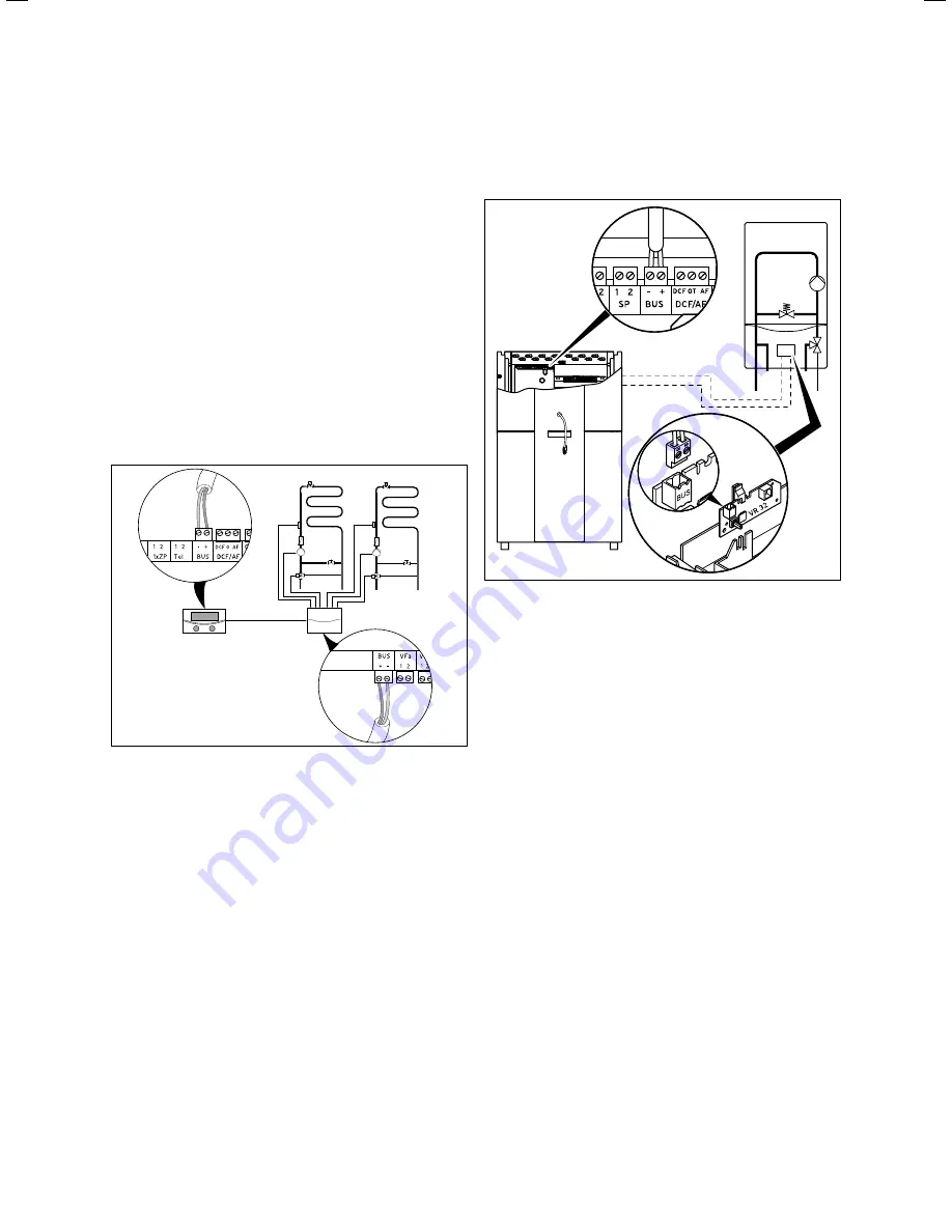
Installing VR 60
With the VR 60 mixer module, you can add two mixed cir-
cuits to the control system of the heating installation. You
can connect a maximum of six mixer modules.
A unique bus address is set on the mixer module by means
of a rotary switch. You can use the operating panel to set
the heating programmes and all of the required parameters.
All heating circuit connections (sensors, pumps) are made
directly to the mixer module with ProE plugs.
For assembly of the VR 60 mixer module, see its enclosed
installation instructions.
Like the VR 90 remote control units, the VR 60 mixer mod-
ules also communicate with the heating controller via the
eBUS.
>
During the installation, you must follow the same proce-
dure that is used to connect remote control units
(
¬
Ch. 7.7.1
).
eBUS
7.22
Installing further mixed circuits with VR 60
>
Information about the system design can be found in
(
¬
Fig. 7.22
). Observe the
¬ installation manual
for the
mixer module.
7.8
Connecting an external boiler
You can use an existing external boiler as an auxiliary
heater.
You can use the VR 32 accessory to connect boilers with
Vaillant eBUS interfaces to the eBUS of the heat pump
(
¬ VR 32 installation instructions
).
Boilers without eBUS interfaces are connected using a cut-
off relay (accessory) and the auxiliary heater contact (
1
)
(
¬
Fig.
7.18
).
i
When connecting an external boiler, it is not pos-
sible to have any legionella protection in the
DHW tank.
7.8.1
Connecting an external boiler with eBUS
interface
7.23 Connecting a boiler with eBUS interface
>
In the external boiler, install the bus coupler VR 32
(
¬ VR 32 installation instructions
).
>
Set the eBUS address switch of the VR 32 to 2.
>
Connect the eBUS cable of the VR 32 bus coupler to the
eBUS interface on the controller PCB of the heat pump
(
11
) (
¬
Fig.
7.18
).
>
After starting up the unit, set the hydraulic integration of
the external boiler as an auxiliary heater (
menu A3
)
(
¬
Tab. 9.9
).
The heat pump switches in the external boiler, depending
on the heat requirement and controller setting.
i
The emergency frost protection function for the
heat pump and a DHW tank remain.


