


Appendix
0020188110_03 recoVAIR Installation and maintenance instructions
21
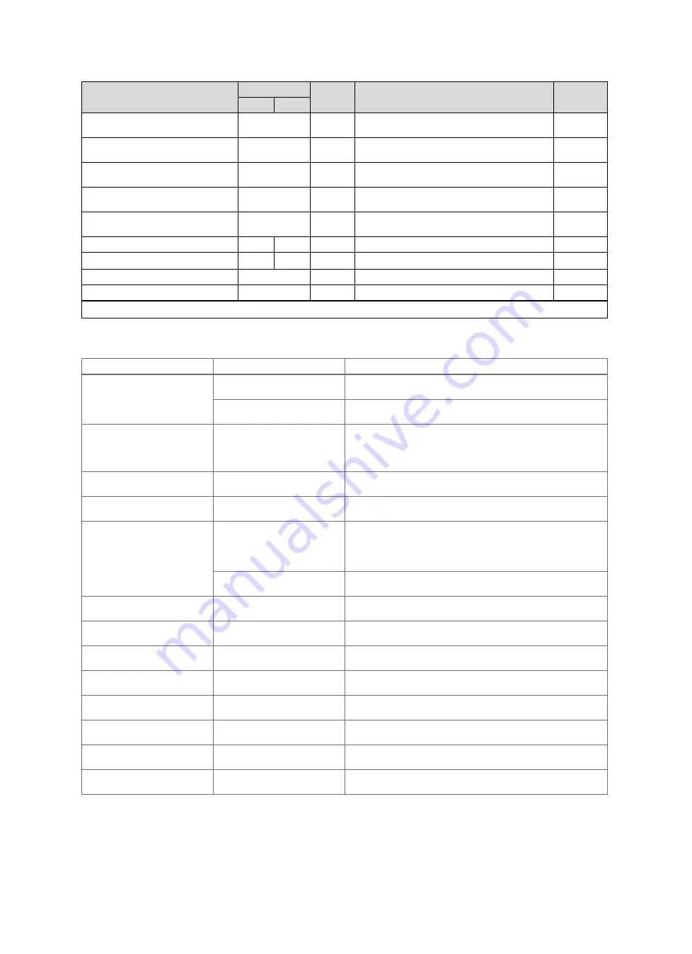
Setting level
Values
Unit
Increment, select
Default
setting
Min.
Max.
Frost prot. element
Not available
,
Electrical
,
Hydraulic
Not avail-
able
Air-earth collector
Not available
,
Available
Not avail-
able
Bypass
Not available
,
Available
Not avail-
able
Pressure monitor
Not available
,
Available
Not avail-
able
Step switch
Not available
,
Available
Not avail-
able
Air quality sensor
0
2
1
0
U value
0.2
2.5
W/(m
2
K)
0.1
1.5
Contact data
Phone number
0 - 9
Close the installation assistant?
Yes
,
Back
1)
Fault lists are only available, and can only be deleted, if faults have occurred.
B
Fault messages
–
Overview
Message
Possible cause
Measure
F.800 Frost protection not
guaranteed
Outside temperature sensor
does not work/is defective
▶
Check that the outside temperature sensor works correctly.
Exit-air temperature sensor
does not work/is defective
▶
Check that the exit-air temperature sensor works correctly.
F.801 Frost protection not
guaranteed
Heat exchanger protection is
active
▶
Wait until the outside temperature increases (the product auto-
matically switches on no later than 60 minutes after the tem-
perature increases.).
Outside temperature: >
−
3
℃
F.802Fault: Ventilator exit air
Exhaust-air fan does not work/is
defective
▶
Check that the exhaust-air fan works correctly.
F.803 Fault: Supply air ventil-
ator
Supply-air fan does not work/is
defective
▶
Check that the supply-air fan works correctly.
F.804 Supply air temp. too
low
Bypass does not work/is defect-
ive
1.
Press the fault clearance key.
–
Fault clearance attempts:
≤
3
2.
If you cannot eliminate the fault with the fault clearance at-
tempt, check that the bypass works correctly.
Heat exchanger does not
work/is defective
▶
Check that the heat exchanger works correctly/has no leak-
ages.
F.805 Air supply temp. of heat
exch. too high
The frost protection element
does not work/is defective
▶
Check that the frost protection element works correctly.
F.806 Fault: Frost prot. ele-
ment
The frost protection element is
defective
▶
Replace the frost protection element.
F.809 Failure: Outside air
temp. sensor
Outside temperature sensor
does not work/is defective
▶
Check that the outside temperature sensor works correctly.
F.810 Failure: Exit air temp.
sensor
Exit-air temperature sensor
does not work/is defective
▶
Check that the exit-air temperature sensor works correctly.
F.811 Failure: Supply air
temp. sensor
Supply-air temperature sensor
does not work/is defective
▶
Check that the supply-air temperature sensor works correctly.
F.812 Failure: Exhaust air
temp. sensor
Exhaust-air temperature sensor
does not work/is defective
▶
Check that the exhaust-air temperature sensor works correctly.
F.815 Fault: Frost prot. ele-
ment
Exhaust-air humidity sensor
does not work/is defective
▶
Check that the exhaust-air humidity sensor works correctly.
F.816 Ventilator connection
inverted
Fan connection incorrect/fan
incorrectly connected/installed
▶
Check the fan connections.


