background image

Appendix

22

Installation and maintenance instructions recoVAIR 0020188110_03

C

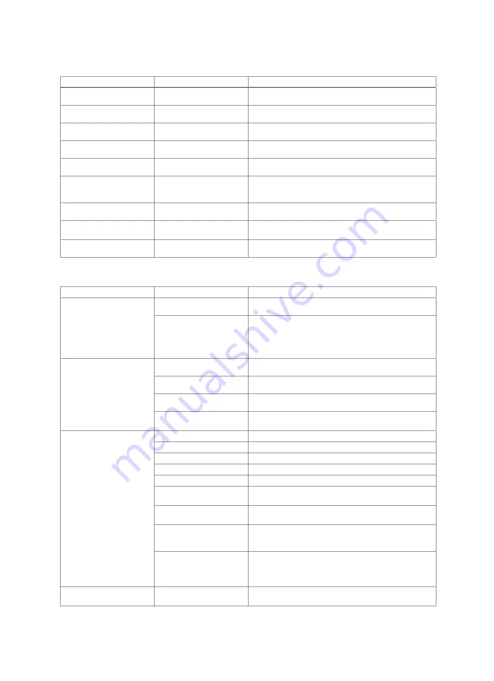
Limp home mode messages

Overview

Message

Possible cause

Measure

Lhm.801 Failure: Exh. air
temp. sensor

Exhaust-air temperature sensor
does not work/is defective

Check that the exhaust-air temperature sensor works correctly.

Lhm.802 Failure: Exit air
sensor

Exit-air temperature sensor
does not work/is defective

Check that the exit-air temperature sensor works correctly.

Lhm.803 Failure: Supply
temp. sensor

Supply-air temperature sensor
does not work/is defective

Check that the supply-air temperature sensor works correctly.

Lhm.804 Failure: Outside air
temp. sensor

Outside temperature sensor
does not work/is defective

Check that the outside temperature sensor works correctly.

Lhm.805 Failure: Exhaust air
humidity sensor

Exhaust-air humidity sensor
does not work/is defective

Check that the exhaust-air humidity sensor works correctly.

Lhm.806 Supply air temp. too
low

Frost protection active

Wait until the supply-air temperature increases again. The
product then starts normal operation.
Supply air temp.: > 10

Lhm.807 Failure/fault: Air
quality sensor

Air quality sensor does not
work/is defective

Check the air quality sensors.

Lhm.810 No connection to
step switch

4-step switch does not work/is
defective

1.

Activate the 4-step switch in the installer level.

2.

Check that the 4-step switch works correctly.

Lhm.817 Failure: Frost prot.
element

The frost protection element is
defective

Replace the frost protection element.

D

Troubleshooting

Symptom

Possible cause

Measure

Product not operating

The mains voltage has been
interrupted/power cut

Wait until the mains voltage has been re-established and the
product automatically switches on (all settings are retained).

Frost protection active (mains
voltage present)

1.

Check whether

S.815

is displayed in the

Live Monitor

.

2.

Wait until the outside temperature increases (the product
automatically switches on no later than 60 minutes after the
temperature increases.).

Outside temperature: >

3

Product with increased noise
level

Missing/incorrect silencer in the
supply-air exhaust-air pipes

Install silencers in accordance with the system planning.

System components (e.g. heat
exchanger, fan) are defective

Replace defective system components.

System components (e.g. heat
exchanger, fan) are dirty

Clean dirty system components.

Fan runs at maximum rotational
speed

1.

Check whether the pressure hoses are bent.

2.

Reduce the air volume flow at the lowest ventilator speed.

No or insufficient exhaust air or
supply air

Filter dirty

Clean the filters.

Exhaust-air line blocked

Clean the exhaust-air line.

Supply-air line blocked

Clean the supply-air line.

Fan defective

Replace the fan(s).

Air flow too low

Install an intake grille that has increased air flow.

Supply-air valve is closed too
far

1.

Open the supply-air valve.

2.

Adjust the system.

Exhaust-air valve is closed too
far

1.

Open the exhaust-air valve.

2.

Adjust the system.

Supply-air temperature too low

Wait until the supply-air temperature increases again. The
product then starts normal operation.
Supply air temp.: > 10

Outside temperature too low

1.

Check whether

S.812

is displayed in the

Live Monitor

.

2.

Wait until the outside temperature increases again. The
product then starts normal operation.

Outside temperature: >

3

Bypass summer mode does not
work

Bypass function not active

1.

Activate the bypass function.

2.

Set the planned operating days for summer mode.

Summary of Contents for recoVAIR VAR 150/4 L

Page 1: ...maintenance instructions recoVAIR VAR 150 4 L VAR 150 4 R AT CH de DE Publisher manufacturer Vaillant GmbH Berghauser Str 40 D 42859 Remscheid Tel 49 21 91 18 0 Fax 49 21 91 18 2810 info vaillant de...

Page 2: ...n element 12 5 3 Connecting the bypass 12 5 4 Connecting the VR 32 bus coupler 12 5 5 Connecting the product to the power supply in a fixed installation 13 6 Operation 13 6 1 Operating concept 13 6 2...

Page 3: ...nd main tenance conditions listed in the instruc tions Any other use that is not specified in these instructions or use beyond that specified in this document shall be considered improper use Any dire...

Page 4: ...lled by at least two people When installing the product secure it against toppling or falling over 1 3 5 Access to the mains plug circuit breaker must be guaranteed Ensure that the mains plug circuit...

Page 5: ...nit 3 1 Symbols on the product Symbol Meaning Opening for the outdoor air filter Opening for the exhaust air filter 3 2 Design 3 2 1 VAR 150 4 R 1 2 3 4 5 6 7 8 15 14 13 12 11 10 9 1 Exhaust air filte...

Page 6: ...flow TMAX Max operating temperature Bar code with serial number The 7th to 16th digits of the serial number form the article number 3 4 CE label The CE label shows that the products comply with the ba...

Page 7: ...ion clear ances when installing on the ceiling 600 400 600 1 Observe the minimum clearances and installation clear ances when installing on the wall Plan sufficient space for installing the ventilatio...

Page 8: ...nd the product If the opening for the exit air pipeline is too close to the inlet opening of the outside air pipeline the exit air can recircu late Prevent exit air from being sucked in directly throu...

Page 9: ...n Risk of material damage caused by con densate If the condensate cannot drain from the product this may damage the product Install the product such that the side of the product with the condensate dr...

Page 10: ...of damage to health caused by incor rectly connected condensate drain pipe work In the interests of hygiene the condensate drain pipework must not be directly connec ted to the waste water piping Con...

Page 11: ...by a missing seal If the pipelines are not connected to the product in way that is vapour diffusion tight condensate may form and damage the product Seal all of the connections for the pipelines to e...

Page 12: ...BUS connection in the con nection area for external components of the product System control installation instructions Connection type eBUS line Controller Compatibility as of VRC 470 4 If the DCF sig...

Page 13: ...verview of the read off and setting options for the in staller level can be found in the Installer level Overview table in the appendix Installer level Overview Page 19 6 2 Calling up the installer le...

Page 14: ...in accordance with the building 0 2 2 5 7 2 13 Recording contact details If you want you can store your telephone number max 16 digits with no spaces in the menu If the telephone number is shorter tha...

Page 15: ...nt options 1 Small wall unit air volume flow 260 m h 2 Large wall unit air volume flow 360 m h 3 Ceiling unit air volume flow 150 m h L variant 4 Ceiling unit air volume flow 150 m h R variant 8 1 Sys...

Page 16: ...rmitted for the product 10 2 Mains connection line defective If the unit s mains connection line is damaged the mains connection line must be replaced by the manufacturer or their customer service dep...

Page 17: ...ating days 182 d Replacement interval reached At least twice annually Replace the filters Exhaust air filter class G4 in accordance with EN 779 ISO Coarse in accordance with ISO 16890 Outdoor air filt...

Page 18: ...ndeckende Kundendienst f r ganz sterreich ist t glich von 0 bis 24 Uhr erreichbar Vaillant Kundendienst techniker sind 365 Tage f r Sie unterwegs sonn und feier tags sterreichweit Applicability Switze...

Page 19: ...el Test menu Check programmes P 01 Bypass test optional Yes No No P 02 Test Frost prot element op tional Yes No No P 03 Initialisation measure Yes No No P 04 System efficiency test Yes No No Installer...

Page 20: ...lable Not avail able Diff temp bypass 0 25 0 5 10 Pressure monitor Not available Available Not avail able Step switch Not available Available Not avail able Air quality sensor 0 2 1 0 Min CO2 content...

Page 21: ...fan does not work is defective Check that the supply air fan works correctly F 804 Supply air temp too low Bypass does not work is defect ive 1 Press the fault clearance key Fault clearance attempts 3...

Page 22: ...power cut Wait until the mains voltage has been re established and the product automatically switches on all settings are retained Frost protection active mains voltage present 1 Check whether S 815 i...

Page 23: ...supply air and exhaust air lines are too close to each other Increase the distances between the openings for the supply air and exhaust air lines Noise transmission between the rooms No T supersonic...

Page 24: ...vailable 684 W 684 W Current consumption 0 37 A 0 37 A Minimum cross section of the supply line 1 5 mm 1 5 mm Protection class 1 1 Level of protection IP10B IP10B Air connection area diameter internal...

Page 25: ...Institute for Civil Engineer ing 84 84 Frost protection mode active prevents freezing and thaws condensate 3 3 Max operating temperature 40 40 Sound power level level 1 at 16 Pa 44 dB A at 46 m 3 h 4...

Page 26: ......

Page 27: ......

Page 28: ...n aus dem Mobilfunknetz ggf abweichende Tarife n here Information erhalten Sie bei Ihrem Mobilnetzbetreiber info vaillant at termin vaillant at www vaillant at www vaillant at werkskundendienst Vailla...

Reviews: