4 Set-up
6
Installation and maintenance instructions recoVAIR 0020188110_03
3.2.3
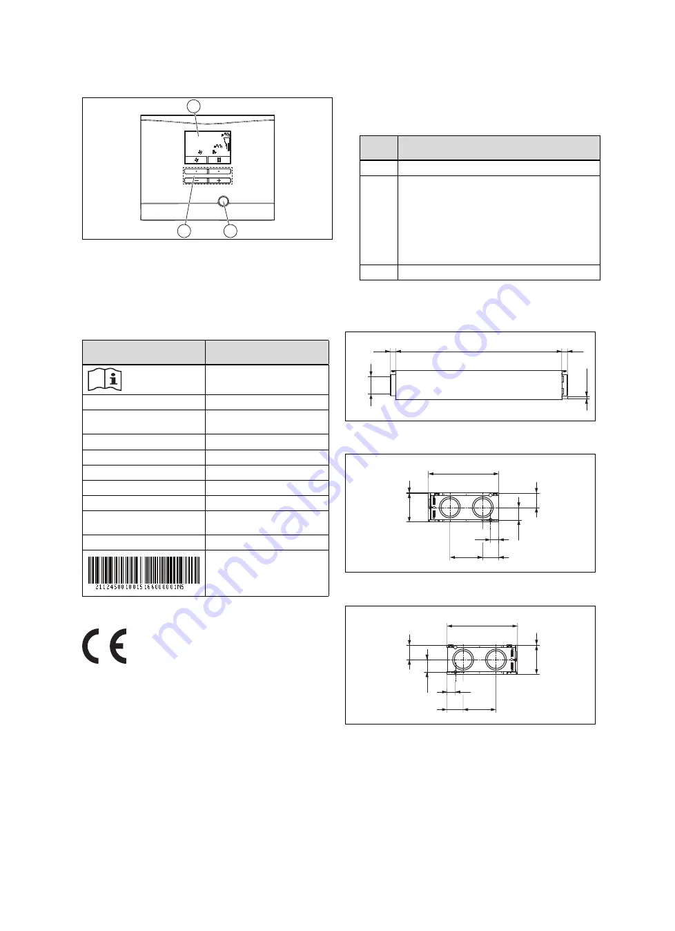
Overview of the operator control elements
100
3
1
2
1
Fault clearance key
2
Operating buttons
3
Display
3.3
Information on the identification plate
The identification plate is mounted on the underside of the
product.
Information on the identific-
ation plate
Meaning
Read the installation and
maintenance instructions.
VAR 150/4 L (R)
Type designation
VAR
Vaillant ventilation unit with
heat recovery
150
Max. air volume flow in m
3
/h
/4
Unit generation
L (R)
Left (right)
P
MAX
Max. power consumption
V
MAX
Max. air volume flow
dP
MAX
Delivery pressure at max. air
volume flow
T
MAX
Max. operating temperature
Bar code with serial number,
The 7th to 16th digits of the
serial number form the article
number
3.4
CE label
The CE label shows that the products comply with the basic
requirements of the applicable directives as stated on the
identification plate.
The declaration of conformity can be viewed at the manufac-
turer's site.
4
Set-up
4.1
Checking the scope of delivery
▶
Check that the scope of delivery is complete.
Quant-
ity
Description
1
Domestic ventilation unit
1
Installation set:
–
Rubber gaskets (4 pcs)
–
Washers (4 pcs)
–
Fixing screws (4 pcs)
–
Rawl plugs (4 pcs)
–
Connection hose for the siphon or condensate
discharge
1
Enclosed documentation
4.2
Dimensions
4.2.1
Front view
Ø 19
Ø 150
(4x)
1413
41
41
4.2.2
Side view from the right
600
246
3
123
106
280 137
71
4.2.3
Side view from the left
600
246
3
123
106
280
137
71


