33
7.1.3 Removal of front casing
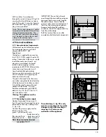
7.1.3.1 Door (fig. 52)
•
Remove bottom hinge screw (1)
and pull the bottom door panel
forwards and down to release it
from top hinge pin (2).
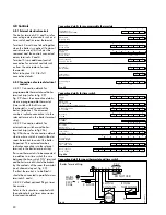
7.1.3.2 Top panel (fig. 53)
•
Slide top panel upwards to release
retaining clips (1).
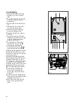
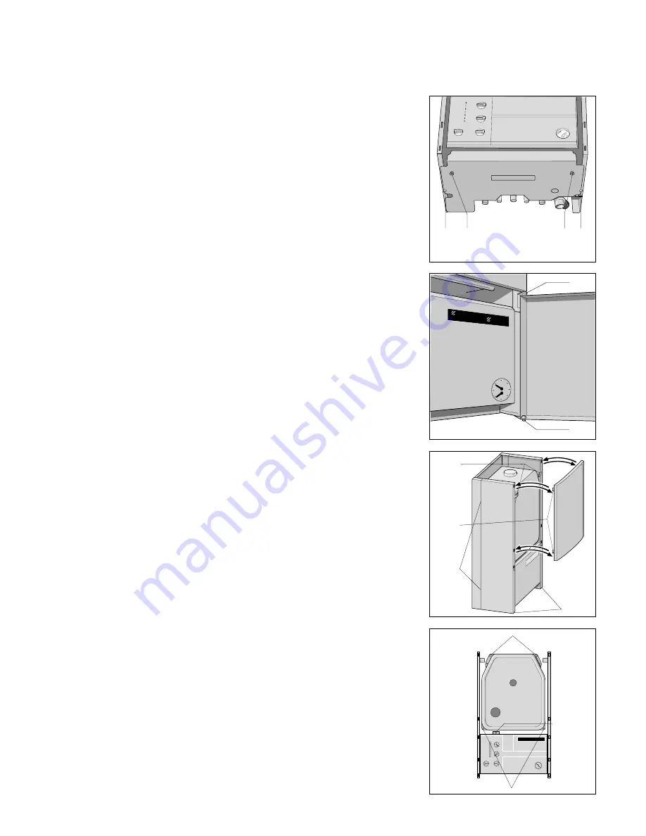
7.1.3.3 Bottom cover plate (fig. 51)
•
Remove two screws (1) and slacken
two screws (2).
•
Slide cover forwards and drop
down to remove
7.1.3.4 Reassembly
•
Reassemble in reverse order.
7.1.4 Removal of side casings
•
Remove front casing as in section
7.1.3.
•
Remove screws (3, fig. 53)
•
Remove screws (4, fig. 53) and
retaining brackets.
•
Slide side case panel upwards to
release retaining clips (2, fig. 53)
and lift off.
•
Reassemble in reverse order
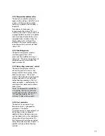
7.1.5 Removal of combustion chamber
cover (fig. 54).
•
Remove front casing as in section
7.1.3,
•
Remove four screws (2) securing
combustion chamber front cover
•
Lift combustion chamber cover clear
of top retaining lugs and pull
forward
•
Remove combustion chamber cover
by first bringing the left side
forward to clear boiler casing.
•
Check condition of case seal and if
necessary replace before refitting
•
Reassemble in reverse order,
ensuring that the combustion
chamber front cover is correctly
fitted and a good seal obtained.
7.1.6 Lower front control panel
(fig. 54)
•
Remove front casing as in section
7.1.3,
•
Undo screw (1) and lower control
box forward from top.
2
1
fig. 52
GW 606/1
4
1
2
3
fig. 53
GW 605/1
1
2
2
fig. 54
GW 613/1
1
1
2
2
fig. 51
GW 1107/1
7.1.7 Removal of heat exchanger
front panel.
•
Remove the five screws (1 and 3,
fig. 47) securing the heat exchanger
and remove the panel by gently
pulling down and forward.

