38
7.9 Replacement of CH
expansion vessel
In the unlikely event of a failure of the
CH expansion vessel follow procedure
7.9.1 or 7.9.2 depending upon the
installation circumstances.
7.9.1. Boiler installed with air/flue
duct to left/right hand side, or
vertical flue installation (where
300mm vertical clearance exists
above the boiler).
•
Remove front casing as in section
7.1.3
•
Turn off the boiler as in section
7.1.1.
•
Release CH water pressure and
drain boiler as in section 7.1.2.
•
Remove combustion chamber cover
as in section 7.1.5
•
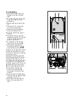
Remove 2 screws (2, fig 63).
•
Remove screw (1, fig. 56) to
release air pressure switch.
•
Slide expansion vessel upwards
and out of boiler casing.
•
Replace in reverse order.
•
Refill and repressurise the boiler
(see section 5.4).
2
4
3
1
1
2
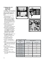
fig. 64
GW 620/1
7.9.2 Boiler installed with air flue duct
to the rear, or vertical flue
installation (where less than
300mm vertical clearance exists
above the boiler)
EITHER
Remove the boiler from the wall as
follows:
•
Remove front casing as in section
7.1.3
•
Turn off the boiler as in section
7.1.1.
•
Release CH water pressure and
drain boiler as in section 7.1.2.
•
Lower front control panel as in
section 7.1.6
•
Disconnect external wiring from
boiler wiring terminal box.
•
Disconnect flow and return
connections at compression
connection above boiler CH service
valves (1, fig. 64).and remove two
screws securing retaining lug to
appliance chassis
(2, fig. 64)
•
Disconnect gas connection at
compression joint on top of gas
service valve (3, fig. 64).
•
Disconnect domestic hot and cold
water connections (4, fig. 64)
•
Disconnect the flue from the top of
boiler as described in section 4.6.
•
Remove boiler from wall.
•
Remove screw (1, fig. 56) to
release air pressure switch.
•
Remove two screws (2, fig. 63) and
slide expansion vessel upwards
and out of boiler casing.
•
Reassemble in reverse order.
•
Re-mount the boiler (see section 4.5
and 4.6).
•
Re-commission the boiler (see
section 5).
OR
A suitable replacement expansion
vessel can be fitted externally to the
boiler as described in Section 3.7.5
(if possible on the central heating
return in an accessible position). In
these circumstances, the replacement
expansion vessel must be correctly
sized ignoring the original expansion
vessel which can be left in position on
the boiler.
2
1
3
fig. 63
GW 639/1


