55
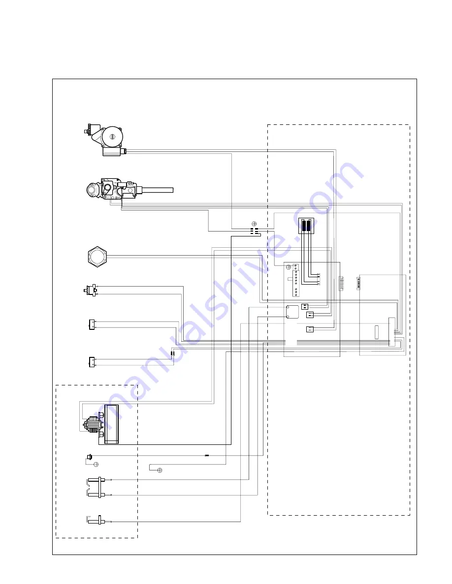
9.2 Wiring diagram: VUW 242/1 E, 282/1 E
fig. 79
GW 1542/0
Combustion chamber
Control box
Flame sensing
electrode
Ignition
electrode
NTC sensor
Fan
Water
switch
Pressure differential
switch
Overheat
thermostat
Air pressure
switch
Gas valve
Pump
Main
transformer
Ignition
transformer
Main
switchboard
Control
board


