Installation 5
0020221303_02 uniSTOR HP Installation and maintenance instructions
13
2.
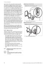
Install a separate power supply for the immersion
heater in accordance with the applicable standards.
3.
Use heat-resistant cables for the immersion heater con-
nection.
–
Diameter of the cable: 1.5 mm
²
4.
Connect the thermal cut-out to the mains power supply
using a double-pole disconnector with a contact gap of
at least 3 mm at both poles.
5.
Protect the electrical circuit using a fuse.
–
Fuse: 13 A
6.
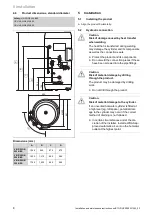
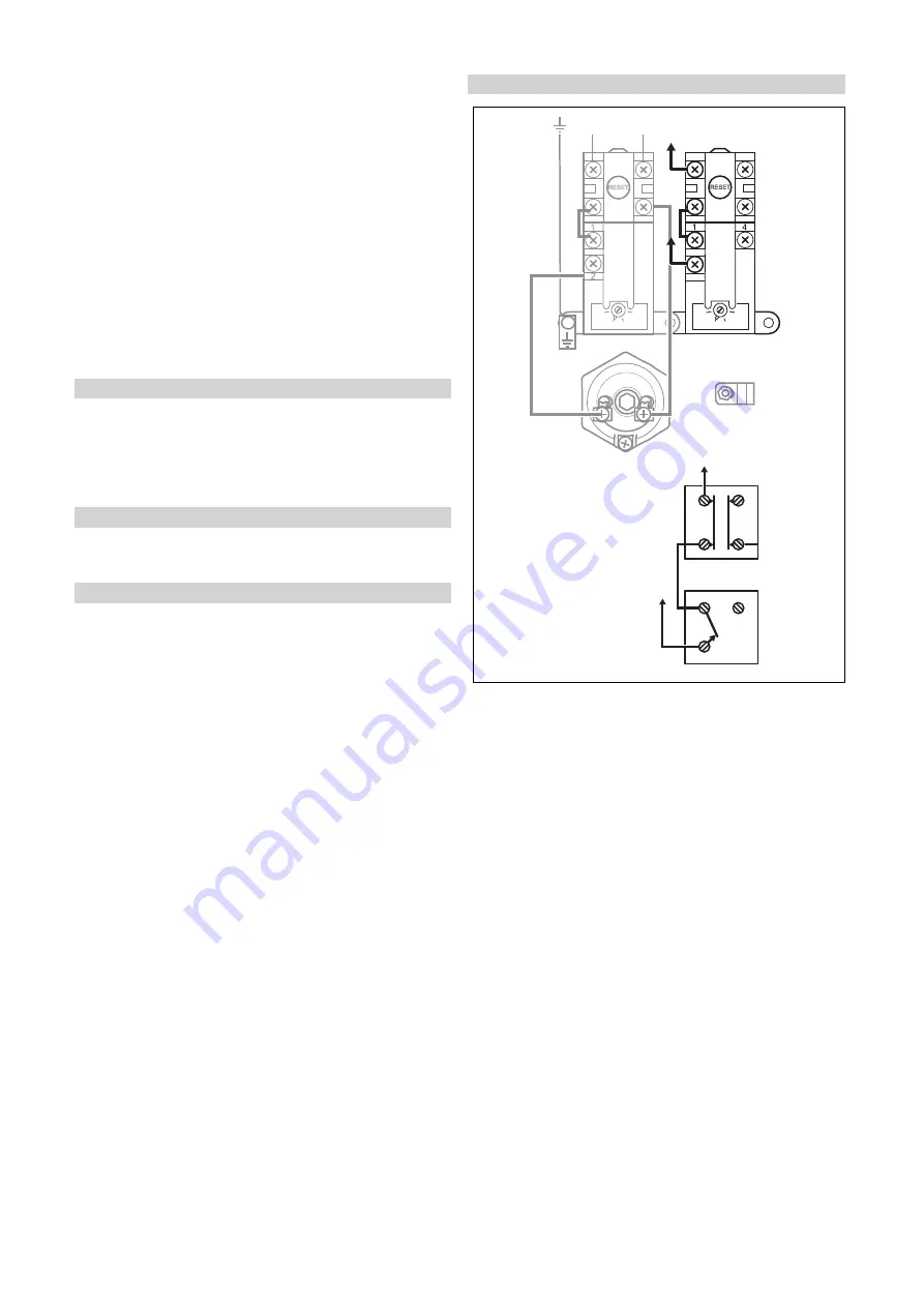
Connect the immersion heater as shown in the basic
diagram.
7.
Attach the cover for the electrics on the cylinder.
5.3.6
Electrical connection of the temperature
sensor
Condition
: With a multi-functional module or control
▶
Connect the temperature sensor to the multi-functional
module or the control; to do this, see the instructions for
the control or multi-functional module.
5.3.7
Connecting the control
Condition
: eBUS
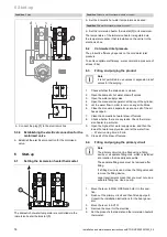
The thermal cut-out for the primary circuit is not used when
connecting an eBUS unit.
Condition
: 230 V control
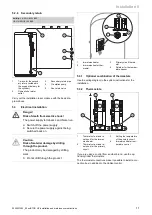
If you use a 230 V control from a third-party manufacturer,
connect the thermal cut-out
(2)
and
(3)
for the primary circuit
to the motorised valve to isolate the heat source in the event
of a fault in the motorised valve.
5.3.8
Electric connection for the primary circuit
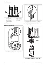
1.
Connect the thermostat for the primary circuit and the
thermal cut-out.
–
Diameter of the cable: 1.5 mm
²
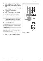
Condition
: S plan
70
60 50
40
70
60 50
40
1
3
2
4
1
3
2
4
L
N
2
1
3
2
2
4
4
1
8
L
8L
8L
SL
▶
Connect the assembly.
Summary of Contents for uniSTOR HP VIH RW GB BES Series
Page 23: ......

