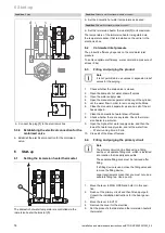
Installation 5
0020221303_02 uniSTOR HP Installation and maintenance instructions
9
5
3
2
1
4
6
8
9
7
10
11
12
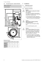
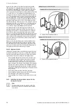
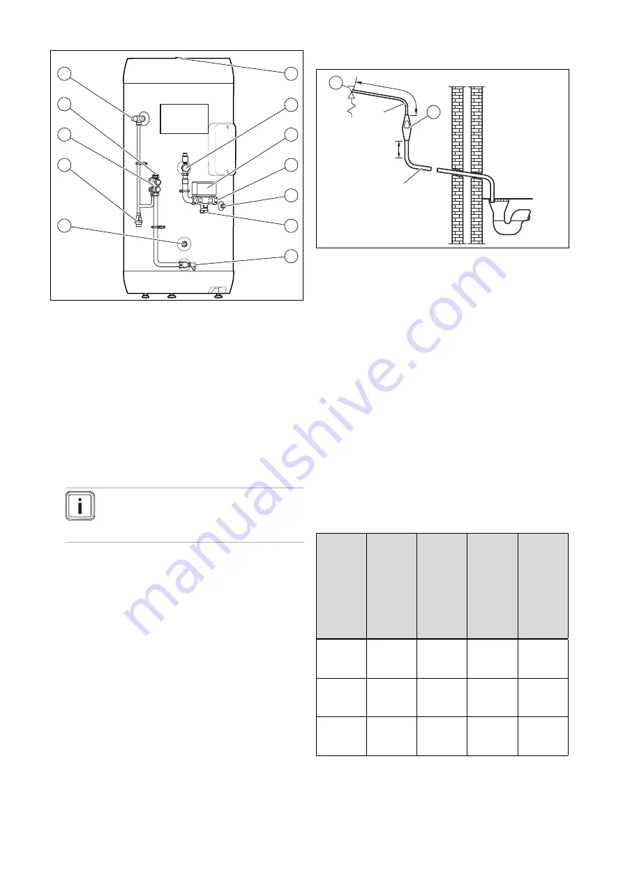
1
Cylinder heating return
2
Tundish
3
Safety group
4
Cold water inlet
5
Domestic hot water
expansion relief valve
6
Domestic hot water
outlet
7
Cylinder heating inlet
8
3-port motorised valve
9
Heating circuit heating
flow
10
Dry pocket for the tem-
perature sensor
11
Heating flow from the
heat pump
12
Drain valve
5.2.1
Connecting the product to the brine circuit
▶
Connect the brine circuit to the product.
–
Minimum diameter of the copper pipe:
≥
28 mm
Note
Ensure that the distance between the heat
generator and the product is as small as pos-
sible in order to prevent heat losses.
5.2.2
Installing an expansion vessel
1.
Install the expansion vessel close to the product.
2.
Install a pipe at the expansion vessel and connect the
terminal to the safety group.
5.2.3
Connecting the installation's cold water
supply
▶
Connect the cold water inlet to the safety group.
5.2.4
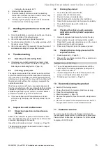
Installing a discharge pipe
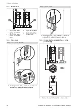
≤ 600 mm
≥ 300 mm
D2
2
1
D1
1
Temperature and pres-
sure expansion relief
valve
2
Tundish
The drain connections of the temperature and pressure re-
lief valve and the expansion relief valve must be connected
to the supplied tundish via 15-mm-thick copper pipes. The
tundish must be installed vertically, as close to the cylinder
as possible and with a maximum clearance of 600 mm from
the connection of the temperature and pressure relief valve.
It must be installed in the same room as the cylinder, but at
a sufficient distance from electrical components. The drain
pipes from the temperature and pressure relief valve and
from the expansion relief valve can be connected above the
tundish using a T-piece. The drain pipe from the 22 mm con-
nection of the tundish must consist of copper pipes with a
diameter of at least 22 mm and be connected to a safe and
visible drainage point. The vertical section of pipe beneath
the tundish must be at least 300 mm long before any bends
or diversions in the line. If the total resistance of the drain
pipework exceeds the values in the following table, you must
increase the diameter of the pipework. When installing the
drain pipework, comply with the standards, directives and
laws that are applicable in your country.
Size of
the outlet
valve
Minimum
diameter
of the
discharge
pipe D1
Minimum
diameter
of the dis-
charge
pipe from
the tun-
dish D2
Maximum
permiss-
ible res-
istance,
inform-
ation
on the
length of
a straight
pipe
Resist-
ance per
elbow or
bend
1/2"
15 mm
22 mm
28 mm
35 mm
9 mm
≤
18 m
≤
27 m
0.8 m
1.0 m
1.4 m
3/4"
22 mm
28 mm
35 mm
42 mm
≤
9 m
≤
18 m
≤
27 m
1.0 m
1.4 m
1.7 m
1"
28 mm
35 mm
42 mm
54 mm
≤
9 m
≤
18 m
≤
27 m
1.4 m
1.7 m
2.3 m
Sample calculation
The following example corresponds to a temperature and
pressure relief valve G1/2 with a drain pipe
(D2)
with four 22
mm elbows and a length of 7 m from the tundish to the drain-
Summary of Contents for uniSTOR HP VIH RW GB BES Series
Page 23: ......

