background image

Split Type Installation Manual

15

EN

6  Wiring Circuit Diagram

6.1 

Mono

Wiring Circuit Diagram 6

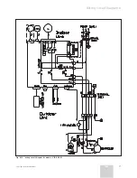
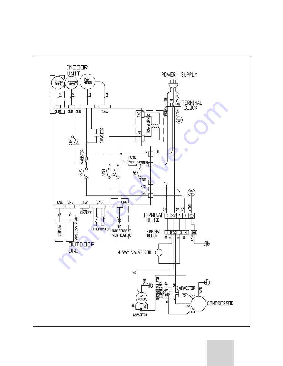
Fig. 6.1.1  wiring circuit diagram for models V 12-025 W and v 12-035 W.

Summary of Contents for V 12-025 HWI

Page 1: ...V 12 025 W V 12 035 W V 12 050 W V 12 060 W V 12 060 M2W Training Manual Air conditioner climaVAIR Split Type EN...

Page 2: ...gle on off 20 7 2 Diagnosis and solution for V12 multi model 060 M2W 25 8 Photographs 28 8 1 Compresor 025 W 28 8 2 Compresor 025 W MULTI 28 8 3 Compresor 035 W 29 8 4 Compresor 035 W MULTI 29 8 5 Com...

Page 3: ...and Table 1 1 depending on the model please consult the model nameplate The dimensions are given in mm Fig 1 1 Dimensions of the indoor unit Legend H Height L Length D Depth MODEL H L D kg V 12 025 H...

Page 4: ...e consult the model nameplate The dimensions are given in mm Fig 1 2 Dimensions of the indoor unit MONO and MULTI Legend H Height L Length D Depth A Length of valves B Distance between valves C Distan...

Page 5: ...tion side opposite couplings minimum 10 cm F Rear separation minimum 10 cm G Lateral separation couplings side minimum 15 cm H Front separation minimum 60 cm 2 Accessories This unit is provided with t...

Page 6: ...n section up to 25 meters mm2 1 5 1 5 2 5 2 5 Inteconnect shielded cable or not YES NO NO NO NO NO Inmediatte residual current protector A 0 03 0 03 0 03 0 03 V 12 060 M2W Power supply V Ph Hz 230 1 5...

Page 7: ...eight and 1m length from the indoor face Outdoor 1m distance from the centre of air outlet Dimensions HxLxD mm 250x745x195 250x745x195 292x900x215 292x900x215 Net weight Kg 9 0 9 0 14 0 14 0 Packaged...

Page 8: ...onditions kW 5 5 Power input UK conditions kW 1 97 Operating current A 8 60 COP 3 22 Energy level class C Max power input kW 2 62 Max operating current A 14 10 INDOOR UNIT Air flow volume m3 h 300 400...

Page 9: ...lves A B C F mm 55 60 142 Dimensions Installation I J mm 400 692 Net weight Kg 64 Packaged dimensions HxLxD mm 690x1050x455 Volume m3 0 330 Packaged weight heat pump Kg 67 INSTALLATION Pipe connection...

Page 10: ...2 91 2 61 2 28 Sensitive capacity kW 2 45 2 45 2 42 2 31 2 21 1 99 1 74 Input kW 0 77 0 85 0 92 1 02 0 98 0 97 0 94 Table 5 1 Cooling temperarures 5 Temperatures by Capacities 5 1 V12 025 W HEATING O...

Page 11: ...3 3 93 3 89 3 70 3 55 3 21 2 82 Sensitive capacity kW 2 96 2 95 2 92 2 79 2 67 2 41 2 12 Input kW 0 92 1 01 1 10 1 21 1 16 1 15 1 11 Table 5 3 Cooling temperarures 5 2 V12 035 W HEATING OUTDOOR TEMPER...

Page 12: ...6 25 6 18 5 88 5 62 5 05 4 40 Sensitive capacity kW 4 74 4 74 4 69 4 46 4 27 3 84 3 35 Input kW 1 44 1 60 1 73 1 91 1 83 1 80 1 75 Table 5 5 Cooling temperarures 5 3 V12 050 W HEATING OUTDOOR TEMPERAT...

Page 13: ...5 7 55 7 48 7 18 6 92 6 35 5 70 Sensitive capacity kW 5 94 5 94 5 89 5 66 5 47 5 04 4 55 Input kW 1 85 2 01 2 14 2 32 2 24 2 21 2 16 Table 5 7 Cooling temperarures 5 4 V12 060 W HEATING OUTDOOR TEMPER...

Page 14: ...38 7 32 7 03 6 79 6 24 5 63 Sensitive capacity kW 5 83 5 82 5 78 5 56 5 38 4 97 4 51 Input kW 1 93 2 08 2 21 2 38 2 31 2 28 2 23 Table 5 9 Cooling temperarures 5 5 V12 060 M2W HEATING OUTDOOR TEMPERA...

Page 15: ...Split Type Installation Manual 15 EN 6 Wiring Circuit Diagram 6 1 Mono Wiring Circuit Diagram 6 Fig 6 1 1 wiring circuit diagram for models V 12 025 W and v 12 035 W...

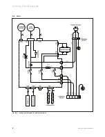
Page 16: ...Split Type Installation Manual 16 Fig 6 1 2 wiring circuit diagram for models V 12 050 W 6 Wiring Circuit Diagram...

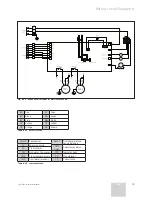
Page 17: ...Split Type Installation Manual 17 EN Wiring Circuit Diagram 6 Fig 6 1 3 wiring circuit diagram for models V 12 060 W...

Page 18: ...Split Type Installation Manual 18 6 Wiring Circuit Diagram 6 2 Multi Fig 6 2 1 wiring circuit diagram for multi indoor units...

Page 19: ...COMP Compressor Duct T Duct temperature sensing device YV Four way valve COMP Delay Compressor delay TR Transformer FM Out warm fan motor LED Indicator light CNB Transformer primary TR Transformer CN...

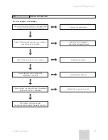
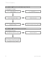
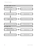
Page 20: ...osis and solution for V12 single on off Indoor environment temperature sensor fault 7 Service Diagnosis E2 Indoor environment temperature sensor fault E2 error diagnosis and solution Check if the resi...

Page 21: ...efrigerant again NO Y E S Check if the coil pipe sensor is normal NO E4 Outdoor unit abnormal E4 error diagnosis and solution Y E S Service Diagnosis 7 Check whether the surface of the condenser is to...

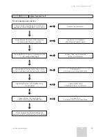
Page 22: ...signal of indoor fan E5 error diagnosis and solution N O 7 Service Diagnosis YES Replace the controlled silicon or indoor PCB Check if the fan motor is broken Check whether the indoor fan is normal Re...

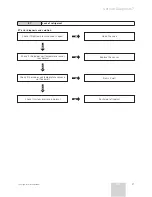
Page 23: ...contact of the inserter on the circuit board and the connection are well Y E S Check whether the signal feedback wire is disconnected Y E S Check whether the supply power is phase lacking or phase opp...

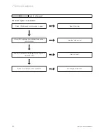
Page 24: ...sensor NO Y E S Check if the indoor coil temperature sensor is not fixed well NO E8 Lack of refrigerant E5 error diagnosis and solution N O 7 Service Diagnosis NO Re fix it well Check if the indoor c...

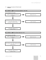
Page 25: ...S 7 2 Diagnosis and solution for V12 multi model 060 M2W Service Diagnosis 7 E2 Indoor environment temperature sensor fault E2 error diagnosis and solution N O Check if the resistance value of sensor...

Page 26: ...n YES E5 PG fan motor failure E3 error diagnosis and solution N O Check if the fan motor is broken Replace the controlled silicon or indoor PCB YES Check if the cross flow fan runs smoothly N O Re fix...

Page 27: ...e sensor NO Y E S NO E7 Lack of refrigerant E7 error diagnosis and solution Check if the indoor coil temperature sensor runs normal Check if the indoor coil temperature sensor is not fixed well Y E S...

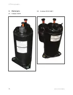
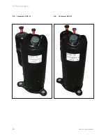
Page 28: ...Split Type Installation Manual 28 8 Photographs 8 Photographs 8 1 Compresor 025 W 8 2 Compresor 025 W MULTI...

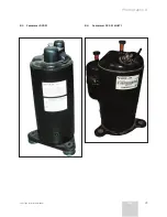
Page 29: ...Split Type Installation Manual 29 EN Photographs 8 8 3 Compresor 035 W 8 4 Compresor 035 W MULTI...

Page 30: ...Split Type Installation Manual 30 8 Photographs 8 5 Compresor 050 W 8 6 Compresor 065 W...

Page 31: ...Split Type Installation Manual 31 EN Photographs 8 8 7 PCB 025 035 MULTI...

Page 32: ...Split Type Installation Manual 32 8 Photographs 8 8 PCB 025 035W MONO...

Page 33: ...Split Type Installation Manual 33 EN Photographs 8 8 9 PCB 050 065W MONO...

Page 34: ...Split Type Installation Manual 34 8 Photographs 8 10 PCB OUTDOOR MULTI...

Page 35: ...temperature protection compressor off temperature TE8 Evaporator high temperature protection fan off temperature PCB Explanation 9 9 1 2 Systematic functions Remote receiving Turbo Position set for i...

Page 36: ...humidifying mode Generally the outdoor fan is turned off with the on off action of compressor in heating mode except for the defrosting mode or the end of defrost Action conditions of compressor under...

Page 37: ...ng mode High wind Mid wind Low wind Slight breeze The default value is 500rpm Cooling mode High wind Mid wind Low wind Note The speed of high wind mid wind and low wind in cooling mode is in line with...

Page 38: ...6 Four way valve working condition it is depended by the running mode 7 Outdoor fan working condition it is depended by the running mode Cooling mode 1 The range of setting temperature 16 C 32 2 Compr...

Page 39: ...fan runs at the high speed The wind speed is neither indicated nor adjustable As for the Jingling common remote controller if you press the HIGH POWER key the air conditioner will begin to run in the...

Page 40: ...higher than 10 C except the indoor fan and the display screen all equipment of the system are not allowed to run 3 Outdoor fan working condition In the dehumidification mode the outdoor fan keeps runn...

Page 41: ...ull closing position is 190 1 When the air conditioner is powered up the air door turns to the full opening position firstly and then turns back 92 and closed 2 When the air conditioner is turned off...

Page 42: ...4 During the high power operating the air conditioner has the anti cold wind function overloading protection and overheating protection function 5 Only when Tp1 meets the setting condition can the air...

Page 43: ...running light which means sleeping screen closed Note Under sleeping operation if the air conditioner accepts the order to adjust the timing time the digital tube will flash which means the system is...

Page 44: ...the buzzer will make different sounds according to the working outputs 1 Power on a single sound buzzing 100ms 2 Turn off a single sound buzzing 100ms 3 A common warning a single sound buzzing 100ms 4...

Page 45: ...the system works well as usual and doesn t display the fault code no matter in which mode it is In heating mode however the dehumidifying operation will be switched to the intelligent dehumidifying m...

Page 46: ...Split Type Installation Manual 46...

Page 47: ...preavviso Vaillant pridr ava pravo na izmjene bez najave Vaillant se reserva el derecho de introducir modificaciones sin previo aviso Vaillant reserves the right to add modifications without prior not...

Page 48: ...GmBH Predstavnistvo u RH Ul Planinska 11 10000 Zagreb Hrvatska Tel 01 61 88 670 61 88 671 Telefax 0 21 931 18 28 10 www vaillant de info vaillant de Vaillant S L C La Granja 26 Pol Industrial Apartad...

Reviews: