20
VAM 6 MWN-I_EN - 09/14 - Vaillant
MAINTENANCE
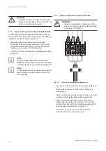
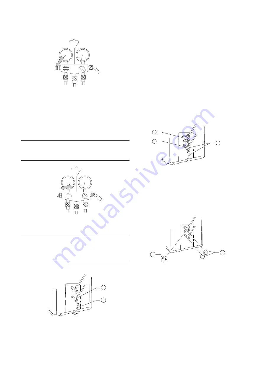
Fig. 12.3
Low pressure manometer reading with the low
valve open
.
• Close the valves on the service manifold and disconnect
the vacuum pump.
• Check the manometer needle after approximately 10-15
minutes have elapsed: the pressure should not rise. If it
does rise, there are leaks in the circuit. Please repeat the
process described on the section 12.1, Checking for leaks
.
a
WARNING!
• Do not proceed to the next step until a satisfactory
evacuation of the installation has been completed.
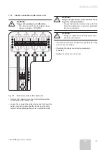
Fig. 12.4
Low pressure manometer reading with the low
valve closed: checking for leaks
.
a
WARNING!
Danger of malfunction and leaks.
• Ensure that the service valves on the outdoor
unit are closed.
12.3
Start up
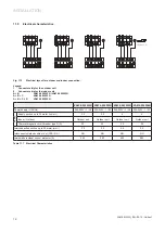
Fig. 12.5
Filling the installation
.
Legend
1 Two-way valve
2
Allen Key
• Open the two-way valve by twisting the allen key 90º
anticlockwise and close it after 6 seconds. The installation
will be filled with coolant.
• Check the installation again for tightness:
-
If there are leaks see section 12.4.
-
If there are no leaks, continue
.
• Remove the service manifold.
• Open the two and three-way service valves by twisting the
allen key anticlockwise as far as it will go
.
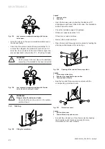
Fig. 12.6
Opening of the two and three-way valves
.
Legend
1 Three-way service valve
2 Allen key (not supplied) to open valves
3 Two-way shut off valve
• Seal the two and three-way service valves with the
corresponding protective covers
.
Fig. 12.7
Protective covers
.
Legend
1 Service hole cover
2 Two and three-way valve covers
• Connect the unit and run it for a few moments checking
that it carries out its functions correctly (for more
information see the user manual)
.
1
2
1
3
2
1
2


