34
Instructions on commissioning, maintenance, and troubleshooting for auroSTOR 0020111119_02
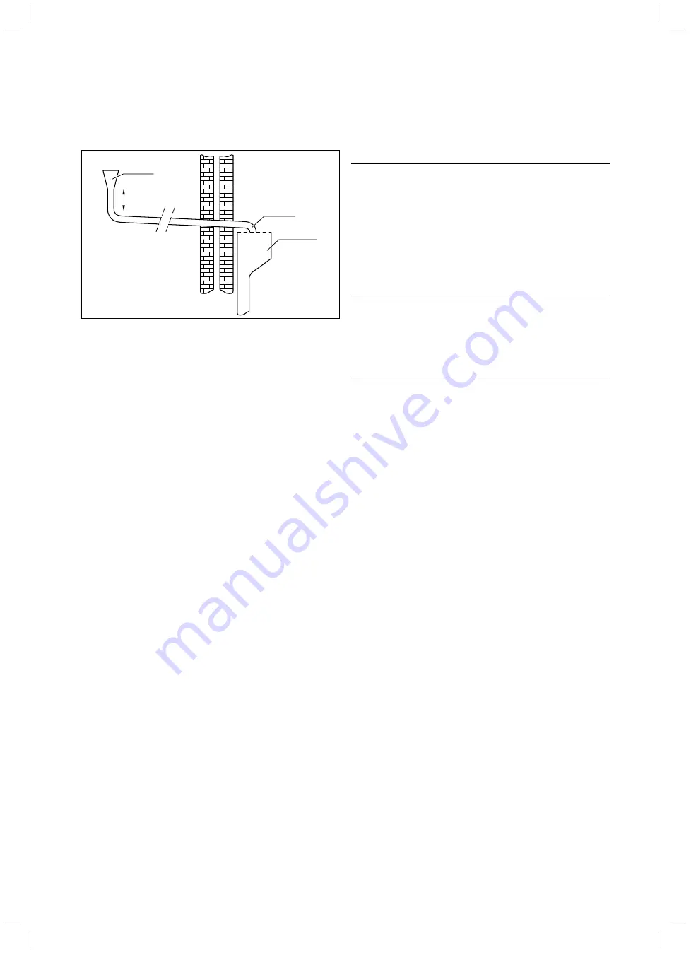
6.7.2 High
drain
tundish
At least
300 mm
Discharge pipe
Metal funnel
Fig. 6.10 High drain connection
The method illustrated in Fig. 6.10 is allowed provided
that no-one inside or outside the building is endangered
by the discharge point.
Examples of points to consider when deciding whether
a location is suitable for the high drain:
– The possibility (taking into account the effect of the
wind) that a person might be located in the area where
the water escapes, and, if this is the case, whether the
water is sufficiently cooled by that point to pose no dan-
ger. Thermal conductivity of the structure's surface, cli-
matic conditions and location and orientation of the
discharge pipe may or may not have an effect on redu-
cing the temperature of the discharge water.
– The position of windows and other openings.
– The probability of prams being parked under the drain.
– The resistance of the surface to hot water.
– The possibility of ice forming if the water is discharged
onto paths.
6.8 Electrical
installation
e
Danger!
Risk of death from electric shock!
Improperly executed electrical connections
can impair the operational safety of the
unit.
>
The electrical installation may only be
performed by a competent person appro-
ved
at the time by the Health and Safety Exe-
cutive.
e
Danger!
Risk of death from electric shock!
Without potential equalisation, life-threat-
ening voltage can reach the piping and
water draw-off points.
>
Earth the heating system.
Wiring should be installed by a qualified competent per-
son in accordance with the building regulations, Part P
of the current IEE regulations, and all other applicable
regulations and directives.
You can use standard commercial cables (H05RR-F 3G1.5
or H05VV-F 3G1.5) for the wiring:
– Cross-section of conductors: 1.5 mm
2
– Torque for strain relief: 1.5 Nm
– Maximum length of bus cables: 300 m
230 V supply lines and bus cables must be laid sepa-
rately above lengths of 10 m.
i
The discharge pipes of the tundish, drain valves
and motorised valves, etc. must be laid at a dis-
tance from electrical components.
6.8.1
Options for combining control components
>
For the installation, use the connection wiring diagram
specified in Tab. 6.5 for the gas-fired wall-hung boiler
and control components used.
Gas-fired wall-hung boiler used
eBUS-compatible gas-fired wall-hung boiler such as the
Vaillant ecoTEC or non-eBUS-compatible gas-fired wall-
hung boiler from Vaillant or a third-party manufacturer.
Wiring
Wiring via the Vaillant VR 61/2 mixer module or
Vaillant
Control Centre as a system solution which enables Vail-
lant dual-channel eBUS controllers (low-voltage) to be
used with valves and domestic hot water cylinders in the
traditional 230 V range in the English market. Alterna-
tively, using a standard cabling box.
6 Installation


