background image

Außerbetriebnahme 11

0020282111_02 VR 100 Installationsanleitung

7

10.2 Leuchtstärke der LEDs

Drücken Sie kurz die Entstörtaste, um
die LEDs aufleuchten zu lassen.

Die LEDs leuchten auf.

Die leuchtenden LEDs zeigen den
Zustand der Kommunikationseinheit
an (Haupt- und Netz-LED).

Die LEDs erlöschen nach 30 Minuten
automatisch.

10.3 Änderung in der Konfiguration

des Heizungssystems
übernehmen

1. Unterbrechen Sie die Stromzufuhr zum

Wärmeerzeuger.

2. Stellen Sie die Stromzufuhr zum

Wärmeerzeuger wieder her.

Die neue Konfiguration des Hei-
zungssystems wird von der Kommu-
nikationseinheit erkannt.

3. Überprüfen Sie den Zustand der

Kommunikationseinheit.
Zustand (Hauptanzeige): Bedeutung
der Haupt-LED (

Seite 9)

Zustand (Signalstärke des Mobilfunk-
netzes / Kommunikation mit Server):
Bedeutung der Netz-LEDs (

Seite 10)

10.4 Registrierungs- oder

Kommunikationsproblem mit
dem Server

Sprechen Sie mit dem autorisierten
Vertreter ab, ob die Kommunikations-
einheit installiert werden soll (Gefahr
der Installation einer Kommunikations-
einheit bei einem inkompatiblen Hei-
zungssystem).

Ergebnis 1:

Positive Antwort

Schließen Sie die Installation ab,
auch wenn der Server nicht antwor-
tet.

Das Problem wird aus der Ferne
ohne Eingriff am Produkt behoben.

Ergebnis 2:

Negative Antwort

Installieren Sie die Kommunikations-
einheit nicht.

11 Außerbetriebnahme

11.1 Kommunikationseinheit

demontieren

1. Unterbrechen Sie die Stromzufuhr zum

Wärmeerzeuger.

2. Trennen Sie die sämtliche Verbindun-

gen.

3. Lösen Sie die Kommunikationseinheit

von ihrem Halter.

4. Lösen Sie die Schrauben des Halters.
5. Entfernen Sie den Halter von der

Wand.

11.2 Recycling und Entsorgung

Überlassen Sie die Entsorgung der
Verpackung dem Fachhandwerker, der
das Produkt installiert hat.

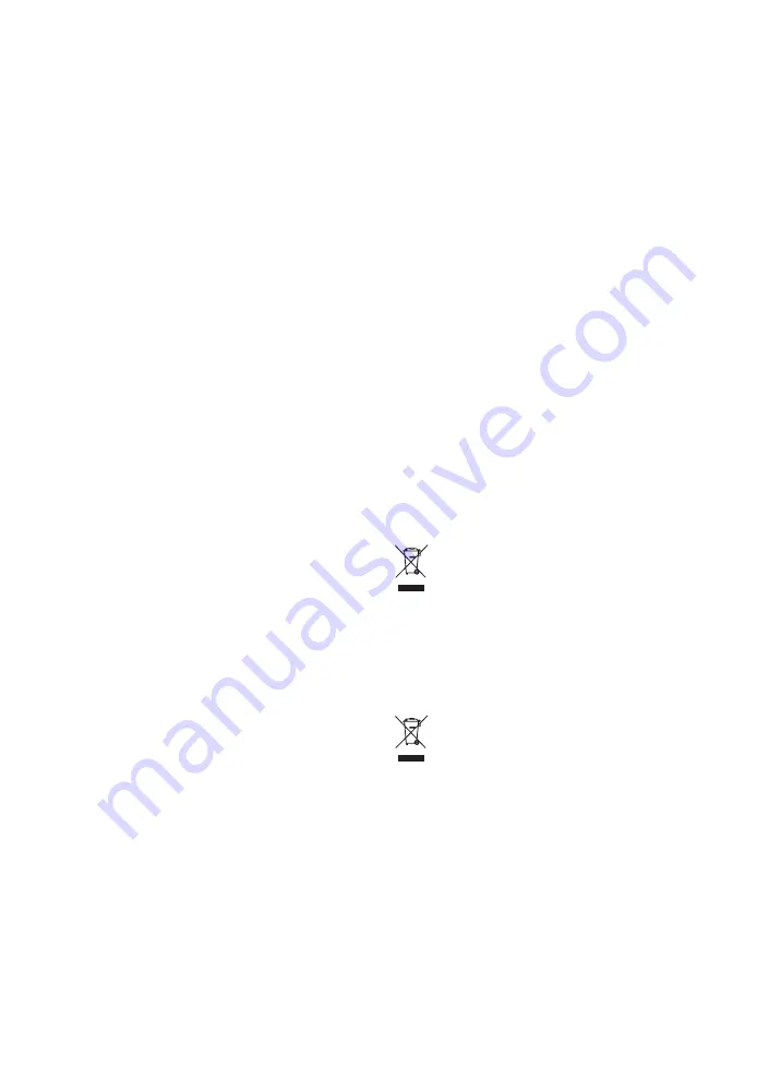
Wenn das Produkt mit diesem Zei-

chen gekennzeichnet ist:

Entsorgen Sie das Produkt in diesem
Fall nicht über den Hausmüll.

Geben Sie stattdessen das Produkt an
einer Sammelstelle für Elektro- oder
Elektronik-Altgeräte ab.

Wenn das Produkt Batterien enthält,

die mit diesem Zeichen gekennzeichnet
sind, dann können die Batterien gesund-
heits- und umweltschädliche Substanzen
enthalten.

Entsorgen Sie die Batterien in diesem
Fall an einer Sammelstelle für Batterien.

Summary of Contents for VR 100

Page 1: ...eitung en Installation instructions nl Installatiehandleiding VR 100 0010025650 Publisher manufacturer Vaillant GmbH Berghauser Str 40 D 42859 Remscheid Tel 492191 18 0 Fax 492191 18 2810 info vaillant de www vaillant de ...

Page 2: ... vaillant co uk VR100 vaillant nl VR100 www vai vg VR100 1 2 X31 X32 230V 24V A B C 3 1 3 2 B C A D 4 0 3 m 5 10 s 7 A C B 6 ...

Page 3: ...C D E F A B 7 C D A B 8 11 9 11 10 A B 1 1 1 1 2 2 2 1 3 3 1 8 8 1 2 2 5 5 1 6 6 1 5 2 2 3 4 4 1 4 2 4 3 7 7 1 7 2 7 3 9 9 1 10 10 1 10 2 11 11 1 10 3 C 10 4 11 2 12 A B A B C B A 11 30 min 12 ...

Page 4: ...de Installationsanleitung 1 en Installation instructions 12 nl Installatiehandleiding 22 ...

Page 5: ...lektroinstallation 5 7 1 Anschluss an Wärmeerzeuger 3 5 7 2 Anschluss an Kommunikationseinheit 4 5 7 3 Anforderungen an den Installationsort 6 5 5 8 Installation in der Wand 6 8 1 Befestigen 7 6 8 2 Überschüssiges Kabel 8 6 9 Inbetriebnahme 6 9 1 Kommunikationseinheit in Betrieb nehmen 12 9 10 11 6 10 Störungsbehebung 6 10 1 Produkt neu starten und Parameter zurücksetzen 6 10 2 Leuchtstärke der LE...

Page 6: ...ie aller weiteren Komponenten der Anlage die Installation und Montage entsprechend der Produkt und Systemzulassung die Einhaltung aller in den Anleitungen aufgeführten In spektions und Wartungsbe dingungen Die bestimmungsgemäße Ver wendung umfasst außerdem die Installation gemäß IP Code Eine andere Verwendung als die in der vorliegenden Anlei tung beschriebene oder eine Verwendung die über die hie...

Page 7: ...lten Sie das Pro dukt spannungsfrei indem Sie alle Stromversorgun gen abschalten elektrische Trennvorrichtung mit min destens 3 mm Kontaktöff nung z B Sicherung oder Leitungsschutzschalter Sichern Sie gegen Wieder einschalten Warten Sie mindestens 3 min bis sich die Kondensatoren entladen haben Prüfen Sie auf Spannungs freiheit 1 2 3 Vorschriften Richtlinien Gesetze Normen Beachten Sie die nationa...

Page 8: ... Sie den oben stehenden Code um die Liste der kompatiblen Wärmeerzeuger und Raumthermo state aufzurufen Die Produkte stehen auf der Liste Installieren Sie die Kommunika tionseinheit Die Produkte stehen nicht auf der Liste Installieren Sie die Kommu nikationseinheit in diesem Fall nicht 4 Produktbeschreibung 4 1 Aufbau der Kommunikationseinheit 1 2 3 4 5 1 Kommunika tionseinheit 2 Wandhalterung 3 H...

Page 9: ...an der Anschluss klemme X31 bzw X32 des Heizgeräts erfolgen Ziehen Sie die Installations anleitung des Heizgeräts zurate um zu ermitteln welche Anschlussklemme vorhanden ist und wo diese sich befin det 3 Schließen Sie das mitgelieferte Kabel an den Wärmeerzeuger an 7 2 Anschluss an Kommunikationseinheit 4 1 Rasten Sie den Wandhalter der Kommunikationseinheit aus 2 Schließen Sie das Kabel 1 an die ...

Page 10: ...e das überschüssige Ka bel nicht ab 6 Bewahren Sie gegebenenfalls über schüssiges Kabel auf Seite 6 8 2 Überschüssiges Kabel 8 1 Wickeln Sie das überschüssige Kabel im Wärmeerzeuger auf 2 Befestigen Sie das überschüssige Ka bel mit dem mitgelieferten Clip und ver gewissern Sie sich dass es nicht mit heißen Komponenten in Berührung kommen kann 3 Stellen Sie die Stromzufuhr zum Wärmeerzeuger wieder ...

Page 11: ... einer Kommunikations einheit bei einem inkompatiblen Hei zungssystem Ergebnis 1 Positive Antwort Schließen Sie die Installation ab auch wenn der Server nicht antwor tet Das Problem wird aus der Ferne ohne Eingriff am Produkt behoben Ergebnis 2 Negative Antwort Installieren Sie die Kommunikations einheit nicht 11 Außerbetriebnahme 11 1 Kommunikationseinheit demontieren 1 Unterbrechen Sie die Strom...

Page 12: ...12 Kundendienst 8 Installationsanleitung VR 100 0020282111_02 12 Kundendienst Gültigkeit Deutschland Auftragsannahme Vaillant Kundendienst 02191 5767901 ...

Page 13: ...kt Starten Sie einmal neu schalten Sie das Hei zungssystem aus und wieder ein Wenn die LED danach länger als 10 Minuten weiter blinkt Sprechen Sie mit dem autorisierten Vertre ter ab ob die Kommunikationseinheit instal liert werden soll Gefahr der Installation einer Kommunikationseinheit bei einem inkompati blen Heizungssystem An grün eBUS Ver bindung ist hergestellt Installieren Sie die Kommunika...

Page 14: ...keine kompatible Rege lung Installieren Sie die Kommunikationseinheit Kapitel 8 Informieren Sie den autorisierten Vertreter darüber dass die Regelung des Heizungs systems inkompatibel ist oder fehlt B Zustand Signalstärke des Mobilfunknetzes Kommunika tion mit Server Bedeutung der Netz LEDs Aktueller Zustand Bedeutung Erläuterung erforderliche Aktivität Hervorragend an grün Hervorragende Mobilfunk...

Page 15: ...nicht erreicht werden Die LEDs zeigen den Zu stand der Mobilfunkver bindung an Sprechen Sie mit dem autorisierten Vertreter ab ob die Kommunikations einheit installiert werden soll Gefahr der Installation einer Kommunika tionseinheit bei einem inkompatiblen Heizungssystem an rot Verbindungsabbruch zum mobilen Kommunikations netz Suchen Sie eine Stelle mit einer bes seren Mobilfunkverbindung Wenn d...

Page 16: ...al installation 16 7 1 Connecting to the heat generator 3 16 7 2 Connecting to the communication unit 4 16 7 3 Requirements for the installation site 6 5 16 8 Installation on the wall 17 8 1 Securing 7 17 8 2 Excess cable 8 17 9 Start up 17 9 1 Starting up the communication unit 12 9 10 11 17 10 Troubleshooting 17 10 1 Restarting the product and resetting parameters 17 10 2 Brightness of the LEDs ...

Page 17: ...he product in accordance with the product and system ap proval compliance with all inspection and maintenance conditions listed in the instructions Intended use also covers in stallation in accordance with the IP code Any other use that is not spe cified in these instructions or use beyond that specified in this document shall be considered improper use Any direct com mercial or industrial use is ...

Page 18: ...switching off all power sup plies electrical partition with a contact gap of at least 3 mm e g fuse or circuit breaker Secure against being switched back on again Wait for at least 3 minutes until the capacitors have dis charged Check that there is no voltage 1 2 3 Regulations directives laws standards Observe the national regula tions standards directives ordinances and laws ...

Page 19: ... to call up the list of compatible heat generat ors and room thermostats The products are included in the list Install the communication unit The products are not included in the list Do not install the commu nication unit in this case 4 Product description 4 1 Design of the communication unit 1 2 3 4 5 1 Communication unit 2 Wall bracket 3 Main LED 4 Network LEDs 5 Reset button for restarting the...

Page 20: ... Connect the enclosed cable to the heat generator 7 2 Connecting to the communication unit 4 1 Unclip the unit mounting bracket from the communication unit 2 Connect the cable 1 to the commu nication unit and in doing so observe the colour code on the sticker 2 below the plug connection 3 The colours of the wires must match the colours on the sticker 3 Re establish the power supply of the heat gen...

Page 21: ...er sup ply of the heat generator The start sequence is triggered automatically The communication unit is initial ising All LEDs light up green main and network LED Not all of the LEDs are green 2 Check the status of the LEDs 3 If faults occur proceed in accordance with the tables in the appendix 4 Allow the LEDs to switch off The LEDs automatically switch off after 30 minutes 10 Troubleshooting 10...

Page 22: ...e heat generator 2 Disconnect all of the electrical connec tions 3 Unmount the communication unit from the retainer 4 Undo the screws on the retainer 5 Remove the retainer from the wall 11 2 Recycling and disposal The competent person who installed your product is responsible for the dis posal of the packaging If the product is labelled with this mark In this case do not dispose of the product wit...

Page 23: ...ive about whether the communication unit should be installed risk of installing a communica tion unit in an incompatible heating system Steady on green eBUS connection is established Install the communication unit Steady on yellow Communic ation unit not registered Agree with the authorised representative about whether the communication unit should be installed risk of installing a communica tion ...

Page 24: ...y on green Excellent mobile connec tion The location for installing the com munication unit is perfectly suitable Install the communication unit Good steady on green Good mobile connection The location for installing the com munication unit is very suitable Install the communication unit Medium steady on green Sufficient mobile connec tion Look for a location with a better mo bile connection If th...

Page 25: ...munication unit in an incompatible heating system Steady on red Loss of connection to the mobile communication network Look for a location with a better mo bile connection If this does not lead to any improve ment and the LEDs continue to light up red do not install the communica tion unit Inform the authorised representative about the problem C Technical data Rated voltage 24 V 10 Rated current 2...

Page 26: ...26 7 Elektrische installatie 26 7 1 Aansluiting op warmteopwekker 3 26 7 2 Aansluiting op de communicatie eenheid 4 26 7 3 Eisen aan de installatielocatie 6 5 26 8 Installatie in de wand 27 8 1 Bevestigen 7 27 8 2 Overtollige kabel 8 27 9 Ingebruikname 27 9 1 Communicatie eenheid in gebruik nemen 12 9 10 11 27 10 Verhelpen van storingen 27 10 1 Product opnieuw starten en parameters resetten 27 10 ...

Page 27: ...an het product en van alle andere componenten van de installatie de installatie en montage con form de product en systeem vergunning het naleven van alle in de handleidingen vermelde in spectie en onderhoudsvoor waarden Het gebruik volgens de voor schriften omvat bovendien de installatie conform de IP code Een ander gebruik dan het in deze handleiding beschreven gebruik of een gebruik dat van het ...

Page 28: ... contact Of schakel het product span ningsvrij door alle stroom voorzieningen uit te schake len elektrische scheidingsin richting met minstens 3 mm contactopening bijv zekering of vermogensveiligheidsscha kelaar Beveilig tegen herinschake len Wacht minstens 3 min tot de condensatoren ontladen zijn Controleer op spanningvrij heid 1 2 3 Voorschriften richtlijnen wetten normen Neem de nationale voors...

Page 29: ...eldigheid Nederland vaillant nl VR100 Scan de code hierboven om de lijst van de compatibele warmteopwek kers en kamerthermostaten op te roe pen De producten staan op de lijst In stalleer de communicatie eenheid De producten staan niet op de lijst Installeer de communicatie eenheid in dit geval niet 4 Productbeschrijving 4 1 Opbouw van de communicatie eenheid 1 2 3 4 5 1 Communicatie eenheid 2 Wand...

Page 30: ...n via de aansluitklem X31 resp X32 het CV toestel worden uitgevoerd Zie de installatiehandlei ding van het CV toestel om te bepa len welke aansluitklem aanwezig is en waar deze zich bevindt 3 Sluit de meegeleverde kabel op de warmteopwekker aan 7 2 Aansluiting op de communicatie eenheid 4 1 Lijn de wandhouder van de communi catie eenheid uit 2 Sluit de kabel 1 aan op de commu nicatie eenheid en le...

Page 31: ... overtollige kabel niet af 6 Bewaar een evt overtollige kabel Pagina 27 8 2 Overtollige kabel 8 1 Wikkel de overtollige kabel in de warm teopwekker op 2 Bevestig de overtollige kabel met de meegeleverde clip en zorg ervoor dat deze niet met hete componenten in aanraking kan komen 3 Breng de stroomtoevoer naar de warm teopwekker opnieuw tot stand 9 Ingebruikname 9 1 Communicatie eenheid in gebruik ...

Page 32: ...tie eenheid moet worden geïnstalleerd ge vaar van de installatie van een commu nicatie eenheid bij een niet compatibel CV systeem Resultaat 1 Positief antwoord Sluit de installatie af ook wanneer de server niet antwoordt Het probleem wordt op afstand zon der ingreep in het product verholpen Resultaat 2 Negatief antwoord Installeer de communicatie eenheid niet 11 Uitbedrijfname 11 1 Communicatie ee...

Page 33: ... 0020282111_02 VR 100 Installatiehandleiding 29 12 Serviceteam Geldigheid Nederland Het Serviceteam dient ter ondersteuning van de installateur en is tijdens kantoor uren te bereiken op nummer Serviceteam 020 5659440 ...

Page 34: ...egenwoor diger af of de communicatie eenheid moet worden geïnstalleerd gevaar van de instal latie van een communicatie eenheid bij een niet compatibel CV systeem Aan groen eBUS verbinding is tot stand ge bracht Installeer de communicatie eenheid Aan geel Communicatie eenheid niet ge registreerd Spreek met de geautoriseerde vertegenwoor diger af of de communicatie eenheid moet worden geïnstalleerd ...

Page 35: ...le foonverbinding De positie is voor de installatie van de communicatie eenheid optimaal geschikt Installeer de communicatie eenheid Goed aan groen Goede mobiele telefoon verbinding De positie is voor de installatie van de communicatie eenheid goed ge schikt Installeer de communicatie eenheid Gemiddeld aan groen Voldoende mobiele tele foonverbinding Zoek een positie met een betere mo biele telefoo...

Page 36: ...unicatie eenheid bij een niet compatibel CV systeem aan rood Verbinding met het mo biele communicatienet werk afgebroken Zoek een positie met een betere mo biele telefoonverbinding Wanneer dit geen verbetering ople vert en de leds blijven rood branden installeer de communicatie eenheid dan niet Informeer de geautoriseerde verte genwoordiger over het probleem C Technische gegevens Ontwerpspanning 2...

Page 37: ......

Page 38: ......

Page 39: ......

Page 40: ...Road Belper 1 1 Derbyshire 1 1 DE56 1JT Telephone 0330 100 3461 info vaillant co uk www vaillant co uk Vaillant Group Netherlands B V Postbus 23250 1100 DT Amsterdam Telefoon 020 5659200 Telefax 020 6969366 Consumentenservice 020 5659420 Serviceteam 020 5659440 info vaillant nl www vaillant nl These instructions or parts thereof are protected by copyright and may be reproduced or distributed only ...

Reviews: