background image

System and product description

Operating and installation instructions  0020249211_03

15

3

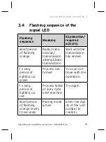
3.4 

Flashing sequence of the 
signal LED

Flashing 
sequence

Meaning

Explanation/ 
required 
activity

Brief period 
of flashing 
orange

Radio trans-
mission/ 
transmission 
attempt/data 
transmission

Wait until the 
transmission 
has ended.

1 x long 
period of 
lighting up 
green

Process con-
firmed

You can con-
tinue with the 
operation.

1 x long 
period of 
lighting up 
red

Process failed 
or duty cycle 
limit reached

Try again.

Brief period 
of flashing 
orange (every 
10 seconds)

Pairing mode 
active

Enter the dig-
its of the unit 
number to 
confirm.

Summary of Contents for VR 52

Page 1: ...erating and installation instructions GB IE Repeater VR 52 Publisher manufacturer Vaillant GmbH Berghauser Str 40 D 42859 Remscheid Tel 49 21 91 18 0 Fax 49 21 91 18 2810 info vaillant de www vaillant de ...

Page 2: ...roduct description 12 3 1 Component of the ambiSENSE system 12 3 2 Design of the product 13 3 3 Radio operation 14 3 4 Flashing sequence of the signal LED 15 3 5 Duty cycle limit 17 3 6 CE marking 18 4 Integration into the ambiSENSE system 19 4 1 Pairing 19 5 Operation 22 5 1 Behaviour following a voltage recovery 22 6 Troubleshooting 23 6 1 Command not confirmed 23 6 2 Resetting to factory settin...

Page 3: ...Contents 3 Operating and installation instructions 0020249211_03 8 Customer service 27 9 Technical data 27 ...

Page 4: ...network Intended use includes the following observance of accompanying operating installation and servicing instructions for the product and any other system components installing and fitting the product in accordance with the product and sys tem approval compliance with all inspection and maintenance conditions listed in the instructions This product can be used by children aged from 8 years and ...

Page 5: ...en must not play with the product Cleaning and user mainte nance work must not be carried out by children unless they are supervised Intended use also covers installation in accordance with the IP class Any other use that is not specified in these instructions or use beyond that specified in this document shall be considered improper use Any direct commercial or industrial use is also deemed to be...

Page 6: ...ric shock The product does not con tain any parts that need to be maintained by the end user The product must only be opened by a competent person If the product shows signs of damage from the outside e g on the housing on control elements on the connection ports or a malfunction occurs the product must not be used In the event of a fault have the product checked by a competent person ...

Page 7: ...sed instructions and all other applicable documents par ticularly the Safety section and the warnings Only carry out the activities for which instructions are provided in these oper ating instructions 1 2 3 Risk of material damage caused by unsuitable environmental conditions The electronics may be damaged if you install the product in an unsuitable envi ronment Only install the product in dry dus...

Page 8: ...ical loads 1 2 4 Risk of material damage caused by an unsuitable plug socket Use the product only in permanently installed earthed plug sockets and not in socket strips or with extension cables You cannot insert any further intermediate plugs into the product 1 2 5 Risk of material damage due to lightning and overvoltage Do not install the product during bad weather ...

Page 9: ... have an on off switch and therefore has to be discon nected from the power grid Only insert the product in a plug socket that is easy to access 1 2 7 Risk of material damage caused by electrical overload An overload may damage the product beyond repair lead to a fire or lead to an electrical accident Before connecting a consumer observe the product s technical data particu larly the maximum power...

Page 10: ...tructions 0020249211_03 1 of the consumers that are being con nected Only load the product up to the speci fied power limit 1 2 8 Regulations directives laws standards Observe the national regulations stand ards directives ordinances and laws ...

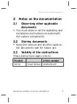
Page 11: ...applicable documents You must observe all the operating and installation instructions included with the system components 2 2 Storing documents Keep this manual and all other applica ble documents safe for future use 2 3 Validity of the instructions These instructions apply only to Product article number VR 52 Great Britain 0020253437 ...

Page 12: ...mate solution can be configured via the VRC 700 app using a smartphone You can use the ambiSENSE repeater to expand the range of the ambiSENSE radio network in order to ensure the communi cation connection between the ambiSENSE units throughout the entire flat or house If you are using ambiSENSE units outside of the direct range of the radio network e g in the cellar or on the top floor of the bui...

Page 13: ...tion Operating and installation instructions 0020249211_03 13 3 two ambiSENSE repeaters in the ambiSENSE system The product is easily paired to the VR 920 Internet gateway 3 2 Design of the product 1 2 1 Repeater 2 System button ...

Page 14: ...efore not be ruled out Interfer ences may for example be caused by switching operations electric motors or defective electrical units The range inside buildings may differ con siderably from the range outdoors Except for the transmission power and the recep tion properties of the transceivers envi ronmental influences such as air humidity and structural elements play an important role on site ...

Page 15: ...shing orange Radio trans mission transmission attempt data transmission Wait until the transmission has ended 1 x long period of lighting up green Process con firmed You can con tinue with the operation 1 x long period of lighting up red Process failed or duty cycle limit reached Try again Brief period of flashing orange every 10 seconds Pairing mode active Enter the dig its of the unit number to ...

Page 16: ...ing sequence Meaning Explanation required activity 6 x long period of flashing red Product defective Note the dis play in your app or con tact your specialist dealer Lights up 1 x orange and 1 x green after plugging into the plug socket Test display Once the test display goes out you can continue ...

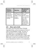
Page 17: ...w software is trans ferred Dura tion Up to 12 hrs This does not affect how the product works during this time 3 5 Duty cycle limit The duty cycle limit describes a legally regulated limit on the transmission time of units in the 868 MHz range The aim of this regulation is to guarantee that all units that work in the 868 MHz range work correctly In the frequency range 868 MHz that is used by the pr...

Page 18: ...during start up or the new installation of a system increased and radio intensive pair ing processes may mean that this limit is not reached If the duty cycle limit is exceeded the signal LED lights up red for one extended period and may indicate that a function is temporarily missing from the product After a short time max one hour the product s function is restored 3 6 CE marking The CE mark sho...

Page 19: ...irec tive 2014 53 EU The complete text for the EU Declaration of Conformity is available at http www vaillant group com doc doc radio equipment directive 4 Integration into the ambiSENSE system 4 1 Pairing To ensure that the ambiSENSE repeater is integrated into the ambiSENSE system and can communicate with other ambiSENSE units it must first be paired to the VR 920 Internet gateway You should the...

Page 20: ...ructions 0020249211_03 5 order to be able to use other ambiSENSE units in the system Then pair the product via the VRC 700 app Open the VRC 700 app on the smart phone Select Settings on the bottom right Select ambiSENSE Select Add Repeater Follow the installation assistant ...

Page 21: ...ons 0020249211_03 21 6 Insert the product into the plug socket If you are prompted to do so by the installation assistant for the app enter the digits of the unit number SGTIN Serialised Global Trade Item Number in the app to confirm or use the smart phone to scan the QR Code ...

Page 22: ...plete The signal LED lights up green The pairing process has been successfully completed The signal LED lights up red The pairing process has failed Try again 5 Operation 5 1 Behaviour following a voltage recovery After inserting the product into a plug socket or recovering the mains voltage the product carries out a self test restart approx 2 sec The LED briefly flashes orange and green LED test ...

Page 23: ...thout any faults the prod uct sends a radio telegram with its status information 6 Troubleshooting 6 1 Command not confirmed If at least one transceiver does not con firm a command the LED signal lights up red once the incorrect transmission is completed The reason for the incorrect transmission may be radio interference caused by one of the following Transceiver cannot be reached Transceiver cann...

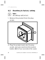
Page 24: ...structions 0020249211_03 6 6 2 Resetting to factory setting i Note All settings will be lost 1 Remove the product from the plug socket 1 2 Plug the product back into the plug socket and press and hold the system button 1 for four seconds at the same ...

Page 25: ... the system button 4 Press the system button again for four seconds until the signal LED lights up green 5 Release the system button to complete the process of restoring the factory set tings The product restarts 7 Decommissioning 7 1 Decommissioning the product 1 Delete the product in the VRC 700 app 2 Remove the product from the plug socket ...

Page 26: ...of the prod uct with the household waste Instead hand in the product to a collec tion centre for old electrical or elec tronic appliances If the product contains batteries that are labelled with this mark these bat teries may contain substances that are hazardous to human health and the envi ronment In this case dispose of the batteries at a collection point for batteries ...

Page 27: ...r customer ser vice are provided on our website 9 Technical data Parameter Value Supply voltage 230 V AC 50 Hz Max load current of the plug socket 8 A Power consumption in standby mode 0 3W Protection class I IP rating IP20 Degree of contamina tion 2 Permissible environ mental temperature 10 35 C Height 70 mm 2 76 in 8 ...

Page 28: ... 76 in Depth 39 mm 1 54 in Weight 154 g 5 43 oz Transmission frequency 868 00 868 60 MHz 869 40 868 65 MHz Maximum transmission power 25 mW Receiver category SRD category 2 Range outdoors 400 m 1 312 ft 4 in Duty cycle 1 per hr 868 00 868 60 MHz 10 per hr 869 40 869 65 MHz Rated surge voltage 2 500 V 9 ...

Page 29: ...Technical data Operating and installation instructions 0020249211_03 29 9 ...

Page 30: ......

Page 31: ......

Page 32: ...copyright and may be reproduced or distributed only with the manufacturer s written consent We reserve the right to make technical changes Supplier Vaillant Ltd Nottingham Road Belper Derbyshire DE56 1JT Telephone 0330 100 3461 info vaillant co uk www vaillant co uk 0020249211_03 ...

Reviews: