4.8.3 Installing
the
DCF receiver with integrated
external sensor
b
Caution!
Danger of material damage as a result of
incorrect fitting!
Incorrect fitting can cause damage to the unit
and/or to the wall of the building, e.g. from
dampness.
Observe the cable routing described and
the correct installation position of the
external sensor.
Drill the wall penetration with a slope to
the outside.
Run the connecting cable with a loop to
catch drips.
Pay attention to the sealing of the DCF
receiver.
The DCF receiver with integrated external sensor may
only be opened by a qualified tradesman and installed in
accordance with the illustrations.
The current safety regulations must be observed as well
as the installation instructions for the boiler and the
heating controller.
2/3
1/3
>1 m
>2 m
>2 m
N, NW
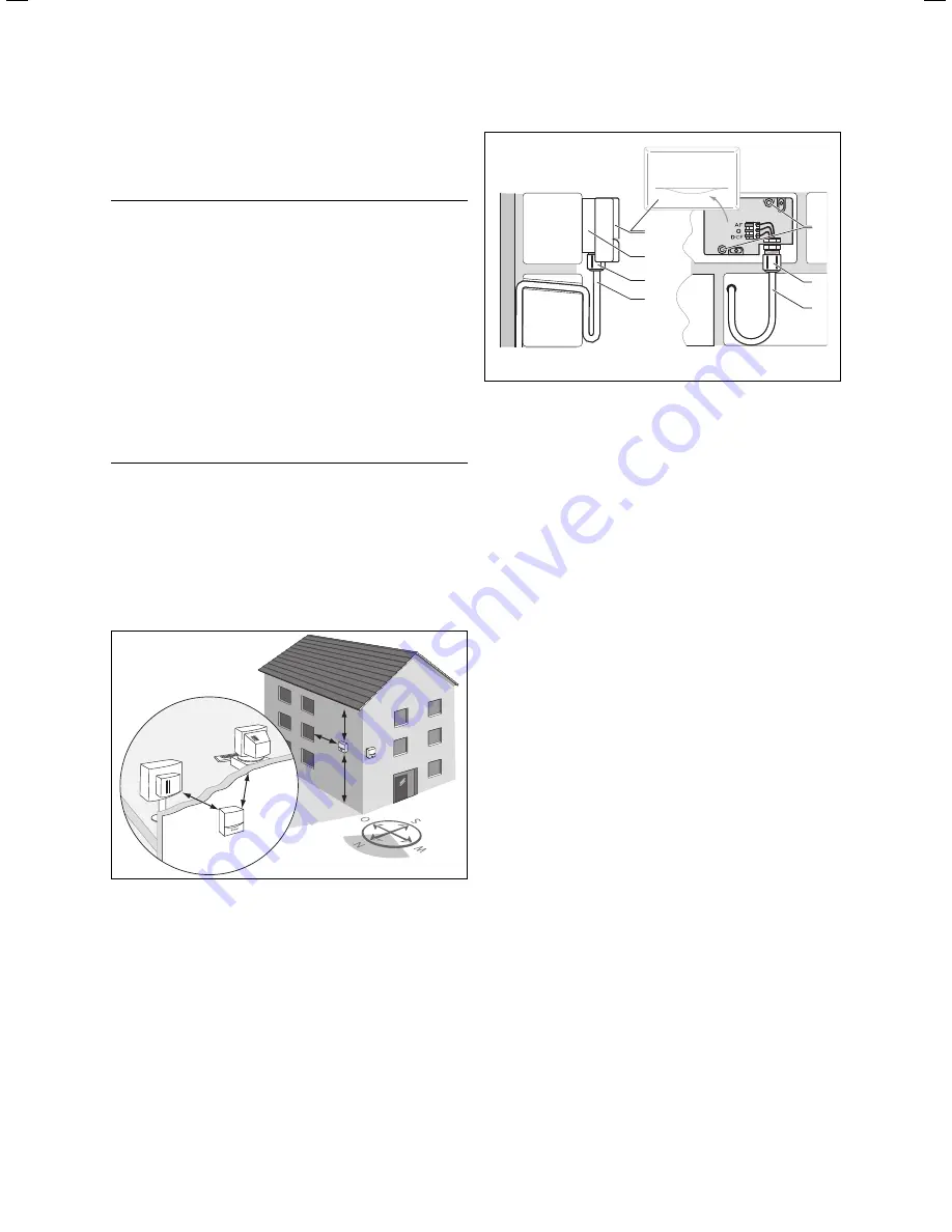
Fig. 4.5 Installation location for the DCF receiver
Observe the requirements for the installation location
(
¬Chap. 4.6
)
>
>
>
>
>
2
4
5
3
2
1
3
Fig. 4.6 Installation location for the DCF receiver
Key
1 Mounting
apertures
2 Cap nut for cable entry point
3 3-core connecting cable with loop to catch drips
4 Wall
base
5 Housing
cover
Carefully plan any holes required for fixing and cable
routing before drilling them.
Mark the position on the wall. Observe the cable rou-
ting for the external sensor.
Route the connection cable (
3
) on the customer side
with a slight incline to the outside and with a loop to
catch drips.
Remove the casing cover (
5
) from the external sen-
sor.
Drill two holes 6 mm diameter to match the fixing
apertures (
1
).
Insert the wall plugs supplied.
Fix the wall socket (
4
) to the wall with two screws.
The cable entry must point downwards.
>
>
>
>
>
>
>
24
Installation Instructions VRC 630 0020095108_00
4 Assembly
Summary of Contents for VRC 630
Page 1: ...GB VRC 630 3 ...
Page 2: ......
Page 54: ......
Page 55: ...For the heating engineer Installation Manual VRC 630 ...
Page 152: ...0020095108_00 GB 022010 Subject to alterations ...


