Appendix
20
Appendix
A
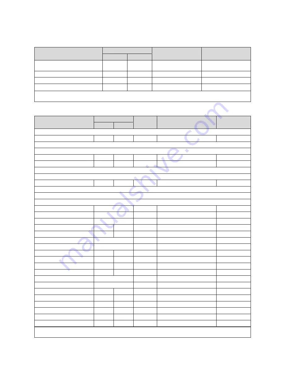
Overview of the setting options
A.1
Installation assistant
Setting
Values
Increment, select
Default setting
Min.
Max.
Language
Languages available for se-
lection
Deutsch
System diagram
1
13
1
1
Config.: VR70, addr. 1
1
12
1
1
System configuration
1)
1) You can use the
OK
button to access the settings for the installer level. You can use the
Back
button to go back one step in the in-
stallation assistant.
A.2
Installer level
Setting level
Values
Unit
Increment, select
Default setting
Min.
Max.
Installer level
→
Enter code
000
999
1
000
Installer level
→
Service information
→
Enter contact details
→
Installer
1
12
Figures
A to Z, 0 to 9, space
Phone number
1
12
Numbers
0 to 9, blank spaces, hyphen
Installer level
→
Service information
→
Service date
→
Next service on
Date
Installer level
→
System configuration
→
System
----
Fault status
Current value*
Water pressure
Current value
bar
System status
Current value
Frost protect. delay
0
12
h
1
4
OT constant heating
Off
, -25
10
℃
1
Off
Controller modules
Display
Software version
Adaptive heat. curve
Current value
Yes
,
No
No
Configure heat. circ.
All
,
Zone
Zone
Automatic cooling
Yes
,
No
No
Start OT cooling
10
30
℃
1
21
Source regeneration
Yes
,
No
No
Curr. room air hum.
Current value
%
1
Current dew point
Current value
℃
1
Hybrid manager
triVAI
,
Biv. point
Bivalence pt
Heat. bivalence point
-30
20
℃
1
0
DHW bivalence point
-20
20
℃
1
-7
Alternative point
Off
, -20
40
℃
1
Off
T. emergency mode
20
80
℃
1
25
Auxiliary heater type
condens.
,
non con.
,
Electric
Calorific value
* If there are no faults, the status is
No fault
. If there is a fault,
Fault list
appears and you can read the fault message in the "Fault mes-
sages" section.
Installation instructions
VRC 700/2
0020200781_01


