2 Notes on the documentation
4
2
Notes on the documentation
2.1
Observing other applicable documents
▶
You must observe all the operating and installation in-
structions included with the system components.
2.2
Storing documents
▶
Pass these instructions and all other applicable docu-
ments on to the system operator.
2.3
Applicability of the instructions
These instructions apply only to:
VRC 700
–
Article number
Great Britain
0020171316
2.4
Nomenclature
The term "heat pump" is used for all heat pumps.
The term "hybrid heat pump" is used when the
VWS 36/4 230 V
or
VWL 35/4 S 230 V
heat pump is being
referred to.
3
Product overview
3.1
CE label
The CE label shows that the products comply with the basic
requirements of the applicable directives as stated on the
identification plate.
The declaration of conformity can be viewed at the manufac-
turer's site.
3.2
Identification plate
The identification plate is located on the product's PCB and
is no longer accessible from the outside after the product has
been installed in the boiler or mounted on a wall in the living
area.
The identification plate contains the following information:
Information on the identific-
ation plate
Meaning
Serial number
For identification
Unit designation
V
Operating voltage
mA
Current consumption
Product complies with
European standards and
directives
Proper disposal of the product
3.3
Checking the scope of delivery
Quantity
Contents
1
Controller
1
VRC 693
outside temperature sensor or
VRC 9535
outside temperature sensor
1
Fastening material (2 bolts and 2 wall plugs)
1
6-way edge connector
1
3-pin pin header connector
1
Operating instructions
1
Installation instructions
▶
Check that the scope of delivery is complete.
4
Installation
You can either install the controller within the boiler or install
it separately on a wall in the living area.
4.1
Installing the controller in the living room
Conditions
: Controller PCB without connected 3
‑
pin header
▶
Install the controller on an interior wall of the main living
room in such a way that perfect recording of the room
temperature is ensured.
–
Installation height: 1.5 m
Ø6
1
2
1
2
3
1
4
1
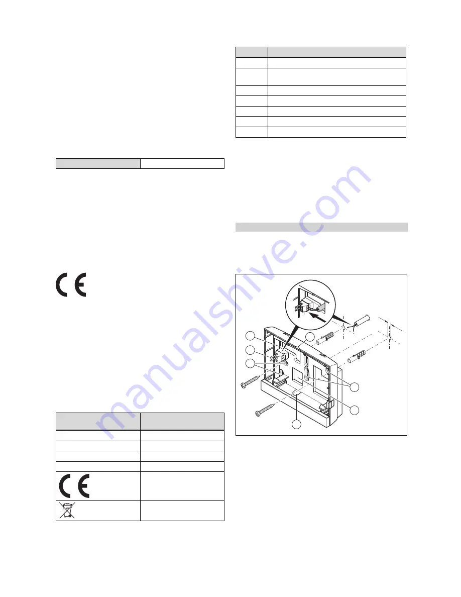
Openings for cable duct
2
Mounting holes
3
Pin header with termin-
als for the eBUS line
4
Opening slot
1.
Screw in the wall socket in accordance with the illustra-
tion.
2.
Connect the eBUS line. (
→
Page 6)
Installation instructions
VRC 700/2
0020200781_01
VR
C 700
/2


