Installation 4
5
3.
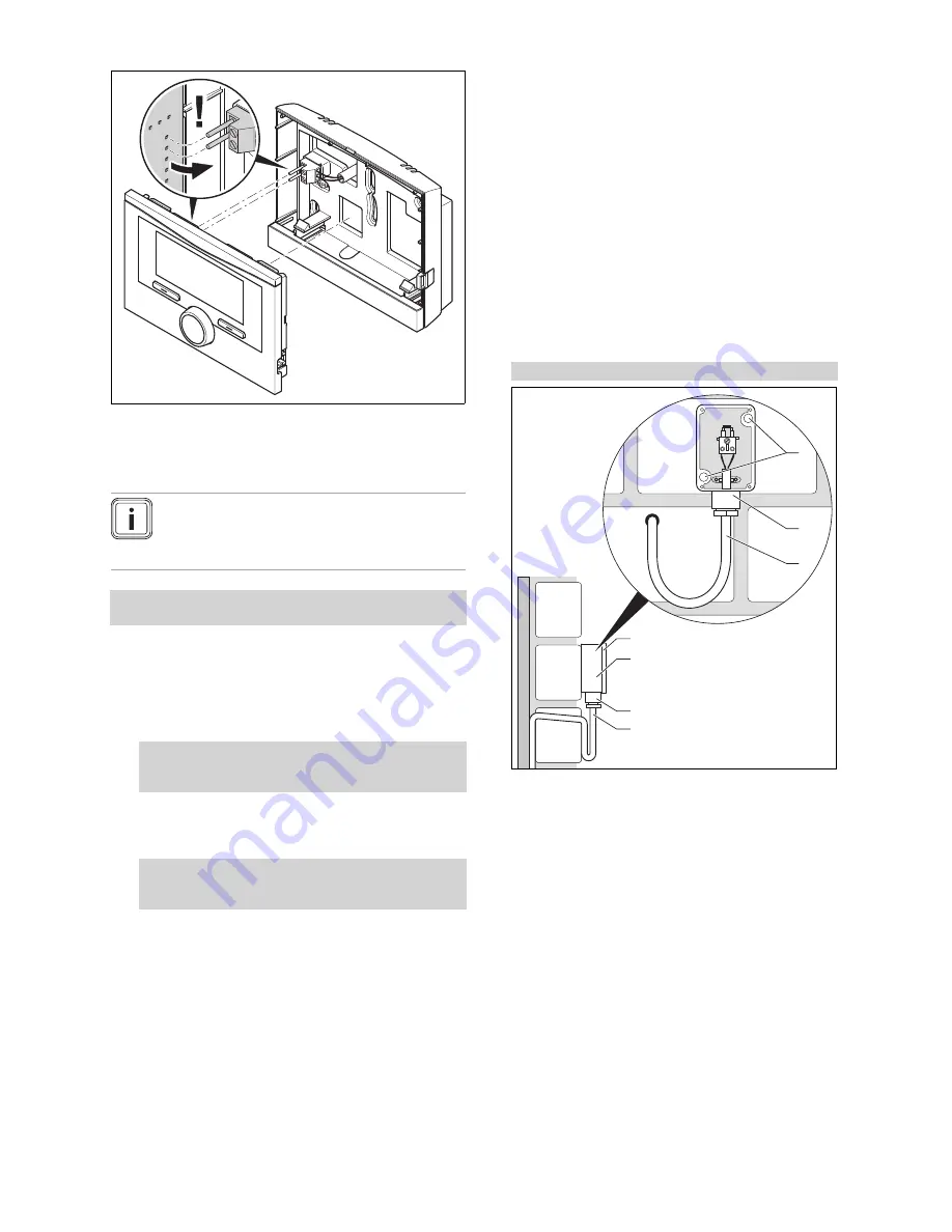
Carefully push the controller into the wall socket.
4.2
Installing the controller in the heat
generator
Note
If you have installed a system with a hybrid heat
pump, you must install the controller in the living
area.
Conditions
: The heat generator is not connected to the eBUS via the
VR 32
.
▶
Remove the operator control screen from the heat gen-
erator for the controller module.
1.
When installing the controller in the heat generator's
electronics box, proceed as described in the installation
instructions for the heat generator.
2.
Alternatives 1 / 2
Conditions
: Vertical plug-in connections with pins in the heat gen-
erator's electronics box, Controller PCB without connected 3
‑
pin
header
▶
Carefully push the controller into the plug connec-
tion of the electronics box.
2.
Alternatives 2 / 2
Conditions
: Horizontal plug-in connections with no pins on the heat
generator's electronics box, Controller PCB with horizontally connec-
ted 3
‑
pin header
▶
Carefully push the controller with the connected 3-
pin header connector into the plug-in connection of
the electronics box.
3.
Connect the outside temperature sensor. (
→
Page 6)
4.3
Installing the outside temperature sensor
The conditions for the installation site are as follows:
–
not fully protected from wind
–
not particularly draughty
–
not in direct sunlight
–
not affected by heat sources
–
on a north or north-west facing façade
–
in buildings with up to three floors, it should be located
two-thirds of the way up the façade
–
in buildings with more than three floors, it should be fitted
between the second and third floor
4.3.1
Installing the outside temperature sensor
1.
Mark the position on the wall.
2.
Alternatives 1 / 2
Conditions
:
VRC 693
outside temperature sensor
5
4
2
3
1
2
3
▶
Drill holes in line with the mounting holes
(1)
.
0020200781_01
VR
C
700/2
Installation instructions


