5 Electrical installation
6
2.
Alternatives 2 / 2
Conditions
:
VRC 9535
outside temperature sensor
2
4
5
3
1
2
3
▶
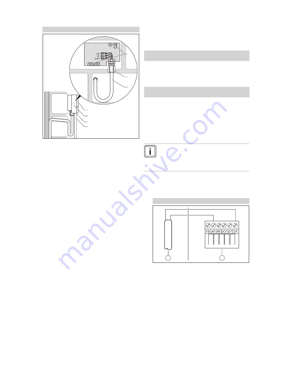
Drill holes in line with the mounting holes
(1)
.
3.
Route the connection cable
(3)
in accordance with the
illustration.
4.
Remove the housing cover
(5)
.
5.
Undo the cap nut
(2)
and slide the connection cable
through the cable duct from below.
6.
Tighten the cap nut.
◁
The seal in the cable duct adapts to the diameter of
the cable used.
7.
Connect the outside temperature sensor. (
→
Page 6)
8.
Place the seal between the wall-mounting base and the
housing cover.
9.
Secure the housing cover.
5
Electrical installation
When connecting the eBUS line, there is no need to pay
attention to the polarity. If the two connections are switched
around, communication is not affected.
5.1
Connecting a controller to the heat
generator
1.
When opening the electronics box in the heat gener-
ator, proceed as described in the installation instruc-
tions for the heat generator.
2.
Connect the eBUS line to the eBUS terminals in the
controller's wall socket.
3.
Connect the eBUS line to the eBUS terminals in the
heat generator.
5.2
Connecting a controller to the ventilation
unit
1.
When connecting the controller to the ventilation unit,
proceed as described in the installation instructions for
the ventilation unit.
Conditions
: Ventilation unit connected to the eBUS without
VR 32
, Ventil-
ation unit without Vaillant heat generator
▶
Connect the eBUS line to the eBUS terminals in the con-
troller's wall socket.
▶
Connect the eBUS line to the eBUS terminals on the
ventilation unit.
Conditions
: Ventilation unit connected to the eBUS with
VR 32
, Ventila-
tion unit with one or more Vaillant heat generators
▶
Connect the eBUS line to the eBUS terminals in the con-
troller's wall socket.
▶
Connect the eBUS line to the common eBUS on the
heat generator.
▶
Set the address switch for the
VR 32
in the ventilation
unit to position 3.
5.3
Connecting the outside temperature sensor
Note
If an additional module has been connected, pay
attention to the instructions for the additional mod-
ule when installing the outside temperature sensor
electrically.
1.
When connecting the outside temperature sensor to the
heat generator's electronics box, proceed as described
in the installation instructions for the heat generator.
2.
Alternatives 1 / 2
Conditions
:
VRC 693
outside temperature sensor
1
2
▶
Connect the connection cable to the terminals on
the outside temperature sensor
(1)
.
Installation instructions
VRC 700/2
0020200781_01


