6
Installation Manual for vrnetDIALOG
- 230 V connection for the power pack sup-
plied
- Installed SIM cardThe card remains the
property of Vaillant, which also pays for it.
Vaillant reserves the right to disable the
card in the event of improper use.
To set up the communication unit you only
need to connect the 230 V power supply.
2.5
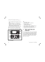
Connections and function elements
3
8
2
1
2
7
3
6
4
5
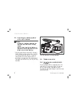
Fig. 2.1 Connections
Key:
1 eBUS diagnostic plug
2 Status indicator (LED) (on the bottom)
3 Bus line connection
4 Telephone network connection
(vrnetDIALOG 820 only)
5 Power supply connection (vrnetDIALOG 830 only)
6 SIM card holder (vrnetDIALOG 830 only)
7 Socket for GSM antenna (vrnetDIALOG 830 only)
8 Earthing terminal (vrnetDIALOG 820 only)
3
Safety instructions and
regulations
The communication unit may only be installed
by an approved heating engineering company,
which is responsible for observing the follow-
ing standards and regulations. We assume no
liability for any damage caused by failure to
observe this manual.
2 Description of the appliance
3 Safety instructions and regulations
Summary of Contents for vrnetDIALOG 820
Page 1: ...vrnetDIALOG 820 vrnetDIALOG 830 vrnetDIALOG DE AT CH BE NL FR TR ES GB ...
Page 2: ......
Page 3: ...Für den Fachhandwerker Installationsanleitung vrnetDIALOG Kommunikationseinheit DE AT CH BE ...
Page 23: ...Voor de installateur Installatiehandleiding vrnetDIALOG Communicatie unit NL BE ...
Page 43: ...Pour l installateur Notice d installation vrnetDIALOG Unité de communication FR BE CH ...
Page 62: ...20 Notice d installation vrnetDIALOG ...
Page 83: ...Uzman tesisatçı için Montaj Kılavuzu vrnetDIALOG İletişim Ünitesi TR ...
Page 102: ...20 vrnetDIALOG Montaj Kılavuzu ...
Page 123: ...For the qualified technician Installation manual vrnetDIALOG Communication unit GB ...
Page 142: ...20 Installation Manual for vrnetDIALOG ...
Page 143: ...21 Installation Manual for vrnetDIALOG GB ...
Page 144: ...839589_00 DE AT CH BE FR NL TR ES GB 04 2005 ...


