Electrical installation 5
0020131957_01 VRT 350 Installation instructions
9
4
3
6
3
2
1
3
4
3
5
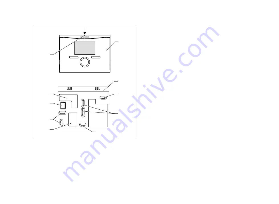
1 Controller
2 Wall-mounting base
3 Mounting holes
4 Openings for cable duct
5 Pin header with terminals
for the eBUS line
6 Slot for screwdriver
2.
Mark the position on the wall. Take the eBUS line route
into account when doing so.
3.
Drill two holes matching the positions of the mounting
holes
(3)
.
–
Diameter of mounting hole: 6 mm
4.
Insert the eBUS line through one of the cable ducts
(4)
.
5.
Insert the wall plugs supplied.
6.
Use the screws supplied to secure the wall-mounting
base.
7.
Connect the eBUS line to the terminal block.
(
→
Page 10)
8.
Carefully insert the controller in the wall mounting base.
Ensure that the pin header
(5)
on the wall-mounting
base fits into the controller connector provided.
9.
Carefully press the controller into the wall-mounting
base until the locking tabs on the controller are heard
to latch into the sides of the wall-mounting base.
5
Electrical installation
When connecting the eBUS line, there is no need to pay at-
tention to the polarity. If the two connections are switched
around, communication is not affected.
If you want to use a
VR 66
, observe the installation instruc-
tions for the
VR 66
Control Centre.


