background image

0020152779_05 - 10/14 - Vaillant

13

EN

REPAIR WORK

5.2 

Installing the casing

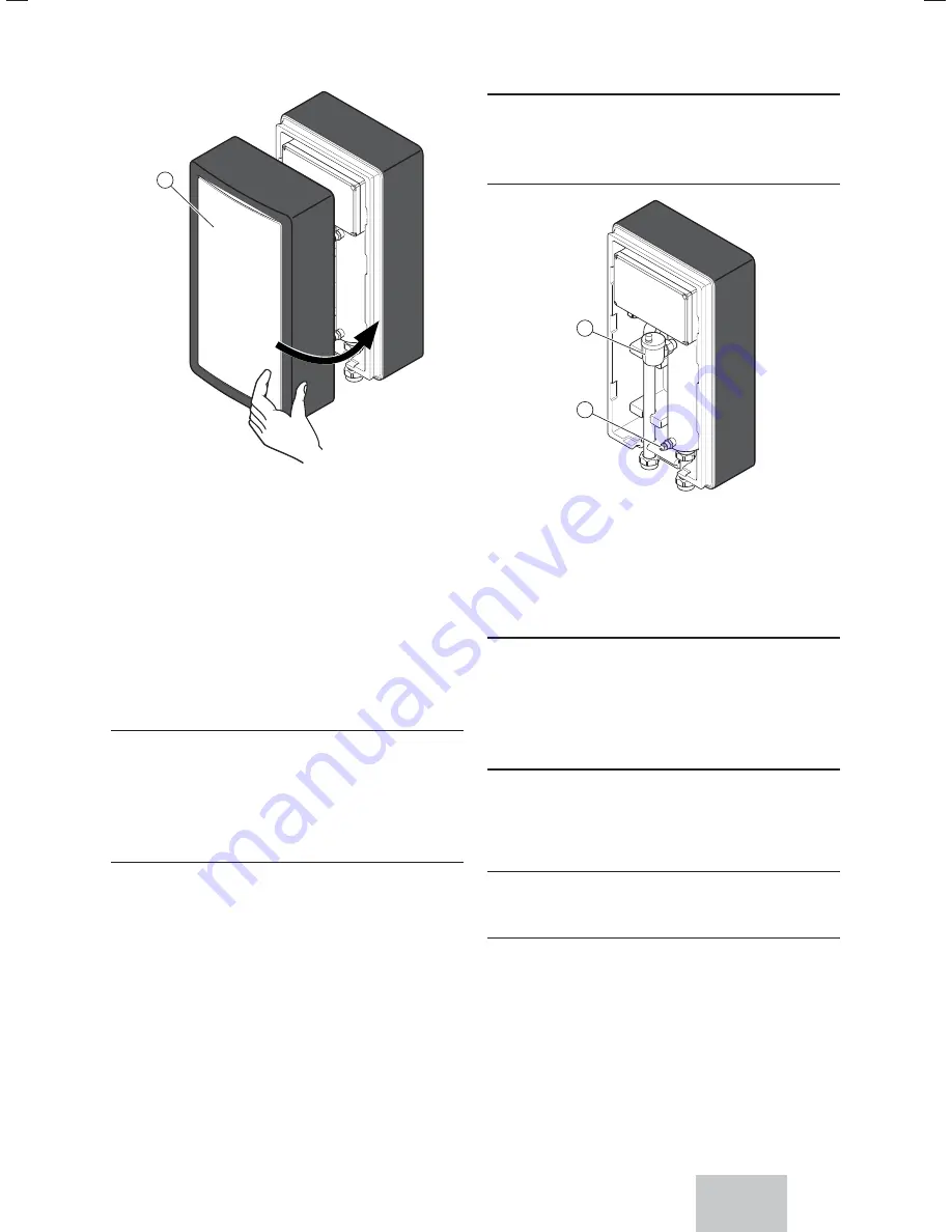
1

1 Front 

casing


Put the front casing back on

5.3 

Handing over the product to the user

After completing the installation:


Answer any questions the user may have.


Draw special attention to the safety instructions which the 
user must follow.

6 Repair 

work

Danger!
Risk of death from electric shock!

Touching live connections may 
cause serious personal injury.


Switch off the electrical supply 
during the maintenance operation.

6.1 Spare 

parts


In case you need spare parts during maintenance or 
repair, exclusively use genuine Vaillant spare parts.

The genuine component parts of the product have been 
certi

fi

 ed together with the product in the course of the CE 

conformity check. If you do not use certi

fi

 ed genuine Vaillant 

spare parts during maintenance or repair, the CE conformity 
of the product will expire. That is why we imperatively 
recommend to install genuine Vaillant spare parts.

6.2  

Draining the product

Caution!
Risk of material damage


Avoid all risk of water projection 
onto the electrical components.

2

1

1 Air 

vent

2 Drainage 

plug


Open the appliance's drainage plug  (2).


Open the appliance's air vent (1).

6.3 

Resetting the Electrical back-up heater

Caution!
Risk of material damage


For this measure, an advance 
check is required and this must 
only be carried out by a 
competent person.

In case of an abnormal increase in water temperature, the 
heating element's safety thermostat may be triggered (Refer 
to the installation manual control box).

It has to be reset manually.

i

 Notes

Let the heating element cool before resetting.

Summary of Contents for VWZ MEH 60

Page 1: ...GB VWZ MEH 60 Installation instructions and instructions for use For the competent person and the operator Installation instructions and instructions for use ...

Page 2: ...number 6 3 3 Data plate description 6 4 Mounting and installation 7 4 1 Preparing the mounting and installation 7 4 2 Mounting the product 8 4 3 Hydraulic installation 8 4 4 Electrical Installation 9 4 5 Cableway and passage 11 5 Start up 12 5 1 Purging the appliance 12 5 2 Installing the casing 13 5 3 Handing over the product to the user 13 6 Repair work 13 6 1 Spare parts 13 6 2 Draining the pro...

Page 3: ...rs 1 4 General safety advices 1 4 1 Danger to life by electric shock Touching live connections can cause serious personal injury Before carrying out any work on the product switch off the power supply Secure the power supply against being switched on again 1 4 2 Danger to life due to missing or not properly working safety devices Missing safety devices can cause life threatening scalding and other...

Page 4: ...tions 1 6 5 1 IMPORTANT Where no British Standards exists materials and equipment should be fit for their purpose and of suitable quality and workmanship The installation of this heating appliance must be carried out by a competent person approved at the time by the Health and Safety Executive and in accordance with the rules in force in the countries of destination Manufacturer s instructions mus...

Page 5: ...e current edition of ETCI rules The heating appliance MUST be connected to a permanent 230V ac 50Hz supply Connection of the whole electrical system of the heating appliance including any heating controls to the electrical supply MUST be through one common isolator and must be fused 30 Amp maximum Isolation should be by a double pole switched fused spur box with a minimum gap of 3mm for both poles...

Page 6: ...ucture 3 1 1 Electrical Module 1 A B 1 Temperature Sensor pocket A Heat input from the heat pump B Heat outlet towards the installation 3 2 Type designation and serial number Data plate location 1 1 Data plate The type designation and the serial number are shown on the data plate 3 3 Data plate description The data plate certifies the country where the product is intended to be installed The data ...

Page 7: ...ting clearances 4 1 2 1 Product and connection dimensions 452 140 140 87 101 447 40 50 50 4 1 2 2 Distance to inflammable parts Make sure that no item that can easily catch fire is in direct contact with the components which may reach a temperature greater than 80 C Make sure that there is a minimum distance of 200 mm between items that can easily catch fire and the hot surfaces 4 1 2 3 Mounting c...

Page 8: ...ht of the product 4 2 Mounting the product 4 2 1 Removing the casing 1 1 Front casing Remove the front casing 1 4 2 2 Wall mounting of the product a Danger Danger to life if the load bearing capacity of the fixing elements used is insufficient If the fixing elements do not have suf ficient load bearing capacity the prod uct can come loose and fall down When fitting the product ensure that the fixi...

Page 9: ...might cause mate rial damage The electrical connection of the product must be carried out only by a suitably qualified person 1 2 30 mm max 1 Electrical wires 2 Insulation When you connect the electrical wires to a connector on the electronic board Keep a distance of a maximum of 30 mm between connector and the start of the insulation If using single core wires are used ensure that they are wrappe...

Page 10: ... mains voltages higher than 400 V electronic components may be destroyed Make sure that the rated voltage of the mains is 400 V Connect alimentation cables of product on the electrical panel of installation 4 4 1 1 Method of collection of electrical cables C A B 4 4 1 2 230 V connection Cable routing 6 kW b Caution Comply with the instructions on the label affixed inside the electri cal casing 02 ...

Page 11: ...Command relay connection 4 4 2 1 With 2 kW electrical booster N N 1 L2 L1 L3 2 1 2 4 4 2 2 With 4 kW electrical booster N N 1 2 L2 L1 L3 1 2 4 4 2 3 With 6 kW electrical booster N N 1 2 L2 L1 L3 1 2 3 4 4 2 4 With multi stage booster N N 1 2 L2 L1 L3 1 2 4kW 2kW 1 Electrical booster module 2 Towards command relay 3 Electrical shunt 4 5 Cableway and passage i Notes The cables must pass through the ...

Page 12: ...t transfer 5 Start up For filling refer to the installation instructions of the heat pump Check the electrical and water installation Check all connections for leaks Fill the heating installation Purge your heating system Replace the power e Danger Risk of death from electric shock Before carrying out the following work ensure that the product has been disconnected from the power supply 5 1 Purgin...

Page 13: ...oduct in the course of the CE conformity check If you do not use certified genuine Vaillant spare parts during maintenance or repair the CE conformity of the product will expire That is why we imperatively recommend to install genuine Vaillant spare parts 6 2 Draining the product b Caution Risk of material damage Avoid all risk of water projection onto the electrical components 2 1 1 Air vent 2 Dr...

Page 14: ...Recycling and disposal The competent person who installed your product is responsible for the disposal of the packaging If the product is identified with this symbol In this case do not dispose of the product with household waste Instead hand in the product to a collection centre for old electrical or electronic appliances If the product contains batteries that are marked with this symbol these ba...

Page 15: ......

Page 16: ...ingham Road Belper Derbyshire DE56 1JT Telephone 0330 100 3461 Vaillant Service Solutions 0330 100 3461 Spares Technical Enquiries 017 73 59 66 15 info vaillant co uk Spares Technical Enquiries technicalspares groupservice co uk www vaillant co uk These instructions or parts thereof are protected by copyright and may be reproduced or distributed only with the manufacturer s written consent ...

Reviews: