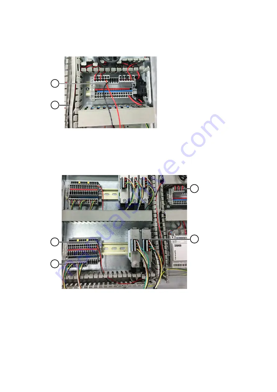
12. Connect the power cable set to the power block located on the right-hand side of the
cabinet.
1
2
1
Vertical cable duct
2
Power cable set connected to power block
13. Route the wires along the cable ducts.
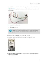
14. The new analog channel terminal blocks are now mounted and connected.
1
3
2
4
1
Logger to analog cable set connected to analog channel terminal block
2
Power cable set connected to analog channel terminal block
3
Power cable set connected to power block
4
Logger to analog cable set connected to data logger
15. Insert any extra length of wire into the cable ducts and replace the cable duct covers.
Chapter 6 – Adding devices to CAB100B
59
Summary of Contents for CAB100
Page 1: ...M212242EN B Installation Guide CMS Industrial Cabinet CAB100...
Page 144: ......
Page 146: ...www vaisala com...


