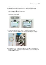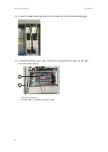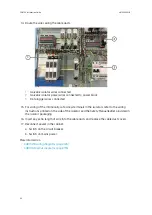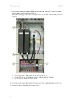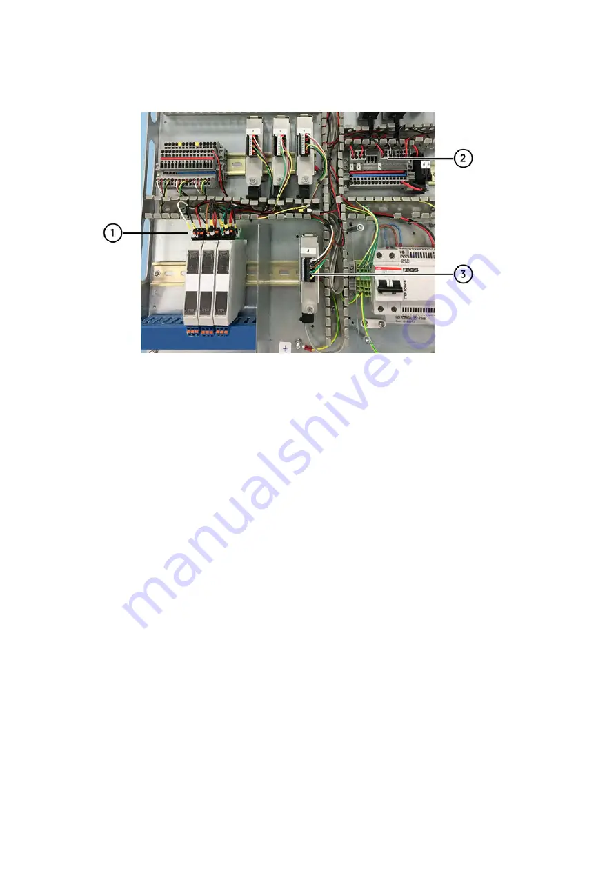
14. Route the wires along the cable ducts.
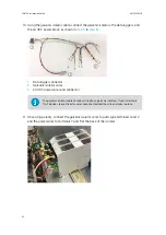
1
Galvanic isolator wires connected
2
Galvanic isolator power wires connected to power block
3
Data logger wires connected
15. For wiring of the intrinsically safe screw terminals in the isolators, refer to the wiring
instructions printed on the side of the isolator and the
Safety Manual
leaflet provided in
the isolator packaging.
16. Insert any extra length of wire into the cable ducts and replace the cable duct covers.
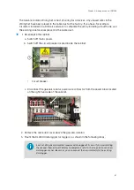
17. Reconnect power in the cabinet.
a. Switch on the circuit breaker.
b. Switch on mains power.
More information
‣
CAB100B wiring diagrams (page 126)
‣
CAB100B layout diagrams (page 135)
CAB100 Installation Guide
M212242EN-B
92
Summary of Contents for CAB100
Page 1: ...M212242EN B Installation Guide CMS Industrial Cabinet CAB100...
Page 144: ......
Page 146: ...www vaisala com...

