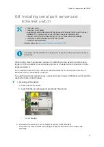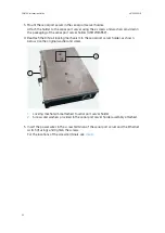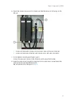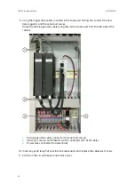
8. Maintenance
8.1 PDT101 calibration
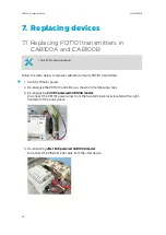
1. Pneumatically connect the transmitter's pressure ports to each other.
The barbed pressure connections accept O.D. 1/4 in × I.D. 1/8 in tubing.
2. Measure the analog output of the transmitter to establish the zero offset reading in the
as-installed position.
3. If the reading is not at the middle of the output range (for example, 12 mA for
4 … 20 mA output), the zero point of the transmitter has shifted.
To remove the zero shift, adjust the transmitter as described in
8.2 PDT101 adjustment
• High accuracy pressure standard and high quality electrical meter for adjustment
• 2.5 mm (3/32 in) flat head or crosshead screwdriver
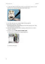
POWER
HI
LO
SPAN
ZERO
Zero adjust
potentiometer
Span adjust
potentiometer
Power LED
Terminal block
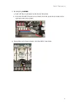
1. Connect the pressure standard to the ports of the PDT101.
2. Bring the pressure to 0 % of the transmitter's span (-60 Pa or -0.25 in H
2
O, depending
on model).
3. Adjust the zero potentiometer (on the front, left side of the transmitter) so that the
analog output value is at the low end of its range.
Use a 2.5 mm (3/32 in) flat head or crosshead screwdriver to turn the potentiometer.
Chapter 8 – Maintenance
107
Summary of Contents for CAB100
Page 1: ...M212242EN B Installation Guide CMS Industrial Cabinet CAB100...
Page 144: ......
Page 146: ...www vaisala com...

