background image

HMD60U/Y 
Operating Manual

HMD60U/Y-U166en-1.2

2

1996-04-12

ELECTRICAL CONNECTIONS


-RH

+T

+RH

-T

T GAIN

RH GAIN

RH OFFSET

T OFFSET

T
TEST

1

2

3

4

5

mA

+

TEST

RH

mA

-

mA

mA

+

-

or

or

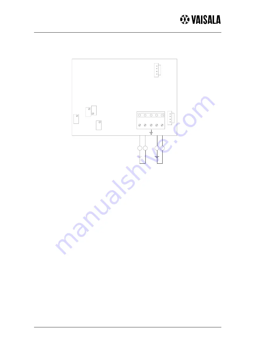
                           Figure 3: Electrical connections

Signal cables are connected to a removeable 5-pole screw connector. Make the
connections according to Figure 3 above. RH test and T test connectors are
used with the HMI41 indicator equipped with an appropriate probe and
optional calibration cable.

Summary of Contents for Humicap HMD60U

Page 1: ...n can be conveniently performed on site with the HMI41 indicator equipped with an appropriate probe and optional calibration cable Figure 1 Dimensions of the HMD60U Y GROUNDING If the cable diameter i...

Page 2: ...ET T TEST 1 2 3 4 5 mA TEST RH mA mA mA or or Figure 3 Electrical connections Signal cables are connected to a removeable 5 pole screw connector Make the connections according to Figure 3 above RH tes...

Page 3: ...racy is recommended to be checked at least once a year the interval depends on the operating conditions and the required accuracy of the measurement The transmitter calibration can be conveniently che...

Page 4: ...ing cast aluminium Cable lead through bushing for 7 10 mm PG9 cable housing IP65 NEMA 4 part no 18941HM or armoured cable glands part no 10528HM Sensor protection standard membrane filter part no 1703...

Page 5: ...RH T X3 X4 UP wet dry HUMICAP sensor sensor Figure 2 Electrical connections Signal cables are connected to a removeable 5 pole screw connector Make the connections according to Figure 2 110 4 33 85 3...

Page 6: ...ge temperature range 40 80 C Long term humidity range for electronics 0 85 RH Housing cover ABS plastic base plate PA Connections Screw terminals 0 5 1 5 mm2 Electromagnetic compatibility The emission...

Page 7: ...rformed on site with the HMI41 indicator equipped with an appropriate probe and optional calibration cable GROUNDING If the cable diameter is less than 7mm use a shrinking tube or an adhesive tape cab...

Page 8: ...SUPPLY HMD70U Y transmitter Controller VAC VAC Us GND signal RH T GND Us RH T signal HMD70U Y transmitter Figure 4 The recommended AC connection HMD70U Y transmitter HMD70U Y transmitter Controller s...

Page 9: ...he accuracy is recommended to be checked at least once a year the interval depends on the operating conditions and the required accuracy of the measurement When checking the transmitter calibration us...

Page 10: ...s less than 0 5 RH without recalibration Operating temperature range electronics 5 55 C sensor head 40 80 C Storage temperature range 40 80 C Housing sensor head stainless steel electronics housing ca...

Page 11: ...te the UP sign which shows the correct mounting position Be careful not to damage the HUMICAP 180 sensor ELECTRICAL CONNECTIONS AND CALIBRATION POTENTIOMETERS RHout Tout Us GND T RH 0 1V 0 5V RH T T R...

Page 12: ...s an increased risk of a short circuit To avoid this use a separate floating supply for each transmitter see Figure 3 However if several transmitters have to share one transformer the phase must alway...

Page 13: ...rs connections An output change causes an error which is less than 0 5 RH without recalibration Operating temperature range 5 55 C Storage temperature range 40 80 C Long term humidity range for electr...

Reviews: