background image


USER'S GUIDE


Vaisala HUMICAP

®

Humidity and 

Temperature Module

HMM212


U338EN-1.2


Summary of Contents for HUMICAP HMM212

Page 1: ...USER S GUIDE Vaisala HUMICAP Humidity and Temperature Module HMM212 U338EN 1 2...

Page 2: ...chanical including photocopying nor may its contents be communicated to a third party without prior written permission of the copyright holder The contents are subject to change without prior notice P...

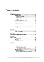
Page 3: ...1 CHAPTER 2 PRODUCT OVERVIEW 13 Introduction to HMM212 13 CHAPTER 3 TO BE NOTED WHEN MEASURING HUMIDITY 15 CHAPTER 4 INSTALLATION 17 Selecting Location 17 Dimensions 18 Electrical Connections 18 CHAPT...

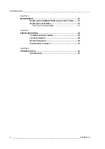
Page 4: ...nsor and the Filter 27 Replacing Consumables 27 Parts List for Consumables 27 CHAPTER 7 TROUBLESHOOTING 29 Troubleshooting Procedure 29 Technical Support 29 Return Instructions 30 Vaisala Service Cent...

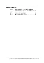
Page 5: ...e between the Ambient Air and the Sensor is 1 C 16 Figure 2 Dimensions in mm inches 18 Figure 3 Electrical Connections of HMM212 Module 19 Figure 4 Calibration Connector for the HMI41 22 Figure 5 Cali...

Page 6: ...able 5 Greenspan s Calibration Table with Output Values According to the Chosen Scale 25 Table 6 Available Spare Parts 27 Table 7 Relative Humidity Specifications 33 Table 8 Temperature Specifications...

Page 7: ...introduces the features and advantages of the Vaisala HUMICAP Humidity and Temperature Module HMM212 Chapter 3 To Be Noted When Measuring Humidity describes issues that need to be noted in the measure...

Page 8: ...es 19164ZZ and 25917ZZ User s Guide M210185EN C Vaisala Humidity Calibrator HMK15 User s Guide General Safety Considerations Throughout the manual important safety considerations are highlighted as fo...

Page 9: ...ion can damage the product or lead to malfunction CAUTION Do not touch the sensor element ESD Protection Electrostatic Discharge ESD can cause immediate or latent damage to electronic circuits Vaisala...

Page 10: ...standards The emission and immunity tests have been performed according to standard EN61326 1 Table 3 Emission Tests Test Setup According to RF field emission CISPR 22 Class B EN55022 Conducted emissi...

Page 11: ...efective Product or part thereof free of charge and otherwise on the same conditions as for the original Product or part without extension to original warranty time Defective parts replaced in accorda...

Page 12: ...ct as well as any adding to it without Vaisala s prior authorization e other factors depending on the Customer or a third party Notwithstanding the aforesaid Vaisala s liability under this clause shal...

Page 13: ...e 4 20 mA loop powered RH and T channels The humidity probe length is an order specified option Furthermore the customer can also order the module with a suitable cable length 0 65 m 1 50 m or 3 0 m a...

Page 14: ...USER S GUIDE____________________________________________________________________ This page intentionally left blank 14 ____________________________________________________________________ U338EN 1 2...

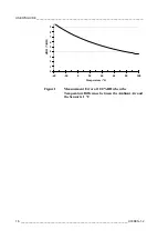
Page 15: ...is 90 RH the error is about 5 4 RH A graph of the measurement error at 100 RH when the temperature difference between ambient air and the sensor is 1 C is presented in Figure 1 on page 16 The error i...

Page 16: ...________ Temperature C dRH RH 0 1 2 3 4 5 6 7 8 9 40 20 0 20 40 60 80 100 Figure 1 Measurement Error at 100 RH when the Temperature Difference between the Ambient Air and the Sensor is 1 C 16 ________...

Page 17: ...mportant for getting representative ambient measurements Select a place that gives a true picture of the environment or process and is as clean as possible Air should flow freely around the sensor Ins...

Page 18: ..._________________________________________ Dimensions Figure 2 Dimensions in mm inches Electrical Connections Connect wires according to Figure 3 on page 19 18 _________________________________________...

Page 19: ...ical Connections of HMM212 Module The following numbers refer to Figure 3 above 1 During normal use leave the jumper as indicated here factory setting 2 Calibration connector for the HMI41 3 Calibrati...

Page 20: ...USER S GUIDE____________________________________________________________________ This page intentionally left blank 20 ____________________________________________________________________ U338EN 1 2...

Page 21: ...tion in the chamber leave the calibrator for example the HMK15 in the chamber overnight with the chamber door open Calibration of a humidity and temperature module allow at least one hour for the stab...

Page 22: ...established the message CON ERROR blinks on the HMI41 display for a couple of times after which measurement readings appear This is quite normal and requires no action however if the message is not re...

Page 23: ...oop and wait until the reading stabilizes 3 Connect a jumper to the RH gain pins and adjust the DMM reading with buttons UP and DOWN until the loop current corresponds to 75 5 RH 4 Disconnect the jump...

Page 24: ...e reading at the first point and repeat the procedure if necessary T offset RH gain WET T gain RH offset DRY Figure 5 Calibration Pins and Pushbuttons With the jumper connected to the RH gain pins eac...

Page 25: ...3 0 5 V V 0 565 0 565 0 565 0 565 0 10 V V 1 13 1 13 1 13 1 13 Temperature NaCl C F RH 15 59 75 6 20 68 75 5 25 77 75 3 30 86 75 1 35 95 74 9 4 20 mA mA 16 10 16 08 16 05 16 02 15 98 0 20 mA mA 15 12...

Page 26: ...libration If for some reason it is necessary to perform the temperature calibration follow attentively the instructions given below Temperature Calibration of an RH and T Module Allow enough time for...

Page 27: ...the sensor by the plastic socket Recalibrate the transmitter CAUTION Do not touch the sensor element Replace a dirty filter to ensure a maximum lifetime and a fast response for the sensor Replacing C...

Page 28: ...USER S GUIDE____________________________________________________________________ This page intentionally left blank 28 ____________________________________________________________________ U338EN 1 2...

Page 29: ...d environment When did it fail date immediately after a while periodically randomly How many failed only one defect other same or similar defects several failures in one unit What was connected to the...

Page 30: ...on page 31 Please have the following information on hand serial number of the unit date and place of purchase or last calibration description of the fault circumstances in which the fault occurs occu...

Page 31: ...ions and adjustments as well as repair and spare part services See contact information below Vaisala Service Centers also offer accredited calibrations maintenance contracts and a calibration reminder...

Page 32: ...USER S GUIDE____________________________________________________________________ This page intentionally left blank 32 ____________________________________________________________________ U338EN 1 2...

Page 33: ...tered filter 60 s Typical temperature dependence of electronics 0 02 RH C Sensor HUMICAP 180R Table 8 Temperature Specifications Property Description Value Measurement range 70 180 C Typical accuracy...

Page 34: ...e Probe Electronics 70 180 C 5 55 C Storage temperature range electronics 40 70 C Sensor protection Standard Stainless steel sintered filter Connections Screw terminals for 0 5 1 5 mm2 wires Table 11...

Page 35: ......

Page 36: ...www vaisala com U338EN...

Reviews: