Mounting
14
VAISALA
Mounting
Depending on your installation requirements, you may wish
to complete the network configuration and setup prior to
mounting (see, Chapter 4 Setup and Operation). Note that
you can complete the configuration and setup procedures
after mounting with a portable PC.
Note:
To connect the HMT140 to your network
and view HMT140 data using viewLinc, you
require HMT140 Utility software and an
HMT140 Configuration Cable (shipped with
viewLinc).
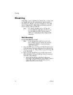
Wall Mounting
To mount the HMT140 on a wall:
Note:
If mounting against a metal surface, be sure to
keep a minimum of 2 mm between the metal and
the back of the HMT140 to ensure an uninter-
rupted radio signal.
1
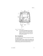
Open the HMT140 cover. Use your thumb to press and
hold the release tab located between the two glands (see
Figure 9 on page 19), then pull the cover out and up with
your other hand.
2
Make sure that the HMT140 is correctly aligned and
attach it directly to the wall with up to four screws (not
included in the package).
• Select the size and type of the fastening screws
according to the wall material (for example, wood or
stone). The diameter of the fastening screws is
typically between 3.5 and 4 mm.
Summary of Contents for HUMICAP HMT140
Page 1: ...86 5 6 GUIDE Vaisala HUMICAP Humidity and Temperature HMT140 Wi Fi Data Logger M211488EN E...
Page 10: ...Regulatory Compliances 6 VAISALA...
Page 16: ...Introduction to the HMT140 12 VAISALA...
Page 26: ...Wiring Diagrams M211488EN E 23...
Page 56: ...Appendix Specifications and Troubleshooting 54 VAISALA HMT140 Dimensions Fixed Probe...
Page 57: ...M211488EN E 55 HMT140 Dimensions Remote Probe...
Page 70: ...www vaisala com M211488EN...


