Chapter 7 _____________________________________________________________ Technical Data
VAISALA _______________________________________________________________________ 167
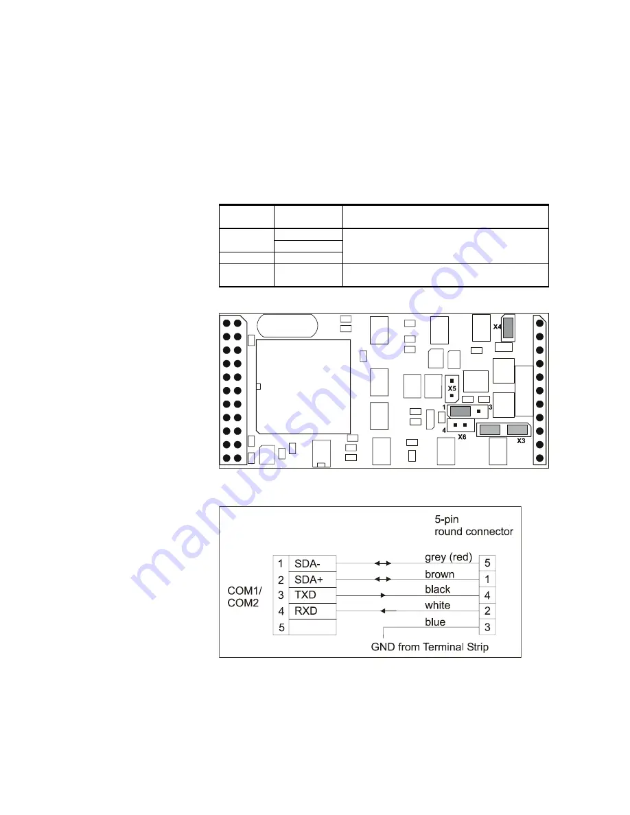
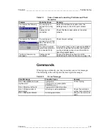
Figure 125 on page 166 provides a schematic wiring diagram for the
dual RS-485 connection, the dual 2-wire connection utilizing both
channels. The correct jumper settings for the channel B are listed in
Table 37 below. The jumpers are located on the module as illustrated
in Figure 126 below.
Table 37
The Jumper Settings for Channel B in the RS-485
Mode
Jumper
Connected
Pins
Function
1-2
X3
3-4
X6
1-2
Sets the RS-485 mode active for the channel
B.
X5
1-2
The line terminating resistor is in use with RS-
485.
0201-049
Figure 126
DSI486 Default Jumper Locations
0201-050
Figure 127
DSI486 Wiring Diagram for RS-485 and RS-232


