10
MI instruction manual
Document/Revision No.
IM-EN-MI
/2.00
Effective: September 2, 2019
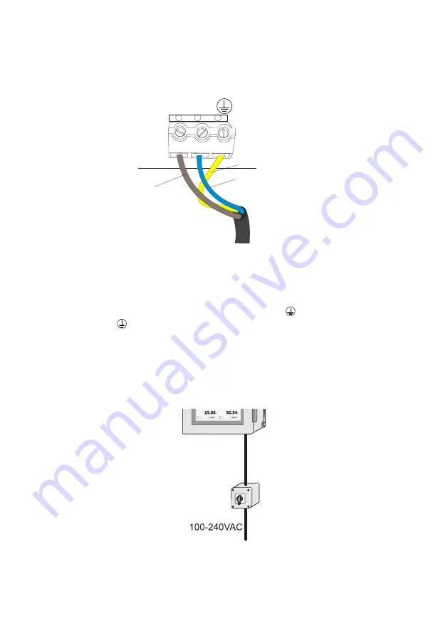
1.L 2.N 3
Brown
Blue
Yellow-green
Figure 3.4
AC power terminals on the motherboard
3.1.2 Power terminals for DC power
The DC power is connected to a terminal stripe in the lower right-hand corner of the
motherboard. The three terminals are marked 1+, 2- and 3
(protective earth). The
power terminal
is directly connected to the exposed metal parts of the MI. The 24V
DC power to this terminal stripe shall be supplied from a secondary circuit which is
double or reinforced insulated from the mains supply within the limits for a limited-
energy circuit (maximum 200 VA/U) according to the IEC 61010-1.
3.1.3 External mains switch
External
mains switch
Figure 3.5
Installing external main switch
Summary of Contents for MI
Page 1: ...IM EN MI v 2 00 Instruction Manual Multichannel User Interface MI ...
Page 4: ...Document Revision No IM EN MI 2 00 Effective September 2 2019 ...
Page 8: ...MI instruction manual Document Revision No IM EN MI 2 00 Effective September 2 2019 ...
Page 11: ...2 Mounting 3 Copyright Vaisala 2019 All rights reserved Figure 2 2 Enclosure dimensions ...
Page 83: ...8 Specifications 75 Copyright Vaisala 2019 All rights reserved 8 2 Parts ...
Page 84: ...76 MI instruction manual Document Revision No IM EN MI 2 00 Effective September 2 2019 ...
Page 86: ...78 MI instruction manual Document Revision No IM EN MI 2 00 Effective September 2 2019 ...
Page 88: ...80 MI instruction manual Document Revision No IM EN MI 2 00 Effective September 2 2019 ...
Page 90: ...82 MI instruction manual Document Revision No IM EN MI 2 00 Effective September 2 2019 ...
Page 92: ...www vaisala com ...


